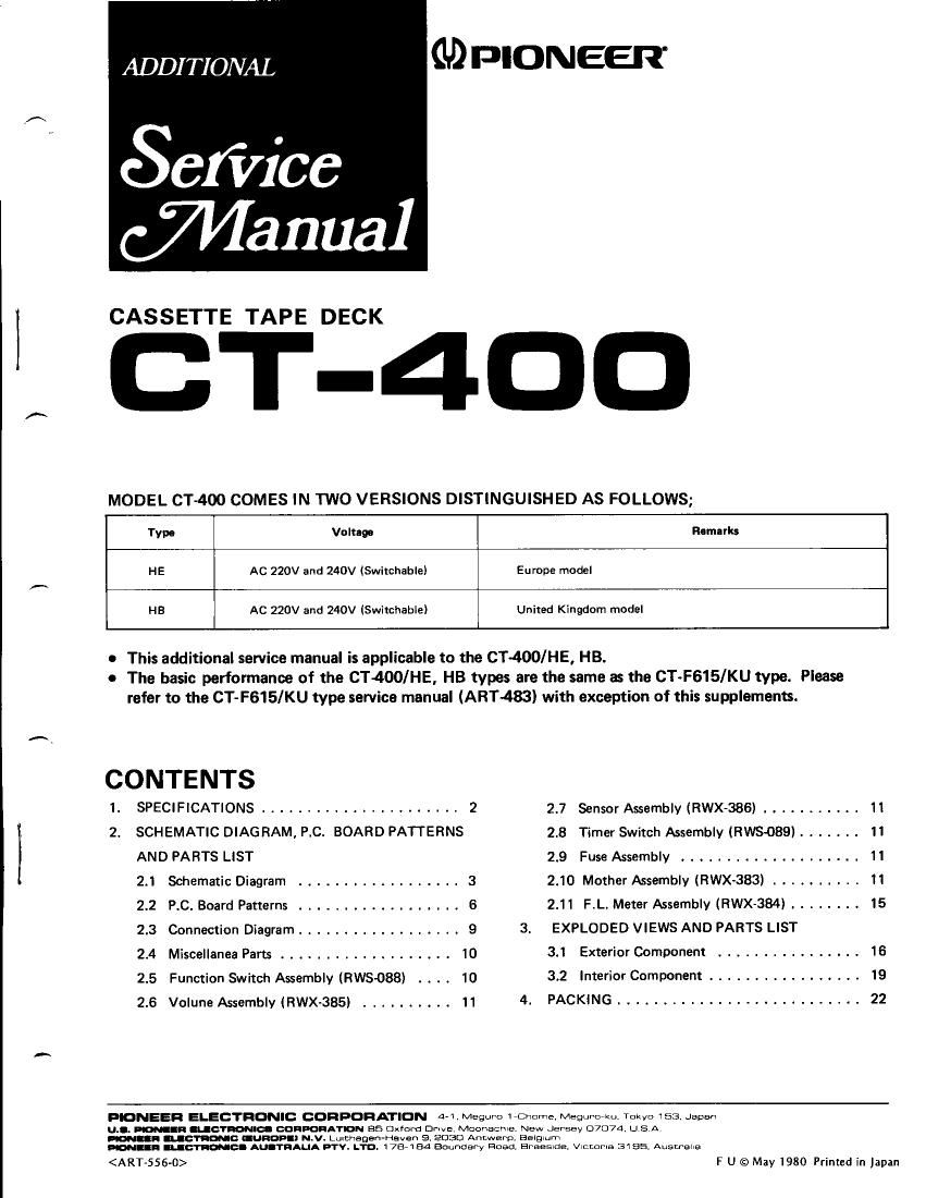
Pioneer ct 400 service manual

This is the 22 pages manual for pioneer ct 400 service manual.
Read or download the pdf for free. If you want to contribute, please mail your pdfs to info@audioservicemanuals.com.

Page: 1 / 22
left right
pioneer ct 400 service manual

Extracted text from pioneer ct 400 service manual (Ocr-read)


Page 1

1. SPECIFICATIONS Systems Motor. . . Heads... ., . . . Compactcassett-ぎ, 2rhannel stereo . . . . .. . Ocservomotorx'l . . "Sendust" recording/playback head x l Erasing head x 1 Fast Winding Time Wow and Flutter Frequency Response Standard, LH tapes ..... ......20 1o 15,000H2 (25 to 14,000H2 -ぎd8) . . . . . .20 to 17,000H2 (25 to 16,000H2 r3dB) ......201017,000H2 (25 to 16,000H2 13dB) Matal tape (odB recording;25 to 8,000H2 13dB) . 20 to 18.00OH2 (25 to 17,000H2 r3dB) (odB recording;25 to 12,500H2 13dB) Signal-to-Noise Ratio DoIbyNROFF ... .... MorethanbgdB DolbyNRON ........ Morethan6SdB (overSkHz) Harmonic Distortion No more than 1.2yo (OdB) Input (Sensilivity/l\4aximum a llowable input/ lm pedance) MIC (L, R) . . . 0.3mV/100mV/1OkQ, 6mm diam. jack (Reference l\,1lC impeadance;250f,, to 1oko) LINE (INPUT) . 50mV/25Vl75kO, Pin jack Output {Reference level/Load impedance) LINE {OUTPUT) . . .4sOmV/sOkO, Pin jack Headphones ....73mV/8Q,6mmdiam.jack Subfunctions o Dolby NR system (ON/OFF) . Stand-by mechanism with unattended recording .4 position rape selector (STD/Fe-CrlcrO, /[/]ETAL) . lC logic control a Full automatic stop mechanism . Air damp eiect function o Fluorescent display level meter (-20 ro +8dB) . REC muting tunction Approximately 100 seconds (C'60 taPe) No more than 0.05% (WRMS) No more than 0.17% (DlN) Miscellaneous Power Requirements ....4C220v1240v (switchable) 50/60H2 Power consumption ,...36watts Oimensions 420(W) x 98{H) x 328(D}mmMax. 16,9/'t 6 x 3-1 /8 x 12.15/ 1 6in Weight (without package) . 6.5kq (14 tb Soz) Furnished Parts Connection cord with pin plugs . .......2 Operating instructions HB model HE model {English, G erman/F rench) Ferrichrome tape Chromium dioxide tape ..... I 2 NOTE: Specifications and ahe design subject to possibte modifications without notice due to improvements, NOTE: 1. Reference Tapes: Standard & LH: DIN 45513/8LATT6 or equav. : CrO2: D1N45513/B LATTT (CrO2 ) or equiv. 2. Reference Recording Level: Meter odB ;ndicating tevet (t60 nwb/m magnetic level = Phillips cassette reference level) 3. Reference Signal: 333H2 4. Wow & Flutter: . JIS [3kHz, with acoustic compensatjon {' reighted), rms valuel . DIN [3,1sOH2, with acoustic com, ponsation ($/eighted) PEAK vatu-ぎl ; DtN 45507 Fr-ぎquency Response: . [,leasured at -20d8 tevet, DOLBY NR OF F, level devialion is t6d8 without indicarion. Signal to Noise Ratio: . Measured at the thard harmonic distortion 3% level, weighted. . Measured at +4dB tevel (250nwb/m magnetic level = DIN 45513 specified reterence levell Sensitiviry: Input level {mV) required Ior reference recording level with input {REC) controls sel to maximum. Maximum Allowable Input: While decr-ぎasing settings ot input (REC) level controls and increasing level at input jacks, this is the maximum input level (mV) at the point where recording amplilier output waveform becomes clipDed, Reference Output Level: Ptayback output level when meter indicates 0dB. 10. This model doesn't employ with a recording/playback con- nector (DlN-typel. *Manufac!ured under licen5e from Dolby Laborarories. *Dolby and !! are trademarks of Dotby Laborarories. 5. 7. 9.

Page 2

a SCHEMATIC DIAGRAM 3i3ii ig!",i;ii,.1il1J i I fu; -{[- ; l l,i6 l::il] lm | '',ffi' ?-T ll'""'F LcH | | llsn+l tt+tREc/PB "'oo -E*7 "tot 'o".. E 44", lnee-ozo | | sr-1 I Lil\E .\ I ouTPUT L'NEIlre I oUTPUT V I lxr:;T'r I lll[;;tr".;} 1*.,"; tuo' r I "o47r I llll ll-'"1. I rrr.re A_1J_L]_ | | f | rueur T-Tfll-l lk[ l"'#l l=e; ' iTlll-l {:'"' il llll"'"'r-"' 'l +++ L t |l Ir: J -]i, l, Q3o3 s#fl ,:::":, 1 b,:::: m | ,,'"";* I',ii"l | /25o | | --'jg--- | ---l-f-=lg- lvR3o1,3o2lrgllBI eras aou | | gllfi lcse-ocz lt SllE | |Igilr- I s::,* i gllE | 'uo lrgllL ,,,-"r, llt 2. 2.1 2 3 \GRAM,P.C.BOARD i:is s6 M,c/LrNE sELcroR ,l-l-^^'--^ Ll:ul - | nr].q t* | | ,ffJ$';sfTJi i'rl I ll+' J]+ PATTERNS AND PA 1"-[l- tlI i1-- olo4'2o4o,:::T.t$T;i:'rt @++]E Q1os,2o5 2SA825-QorR | | | ll_t 'UTLEVEL or2SAb64-RorS llllll cv-o80 lll llk --ttttI 125 | | Lior MPXFTLTER | | ll -"- f:n' I i.; fft llll"' i l',., r'r"ll lH ,/16t Mt Zzp LtI'l i fptlffi L"tro Ir^J1-9J |nrsr ll ll ll.-;;;- rce unless otherwise noted k : kil. t: r1Oo/o tolerance e (V) unless otherwise noted p : pF 0V except electrolytic capacitor. 3. VOLTAGE1] ; DC voltage (V) at no input signal 4. OTHERS:@ : Adiusting point. The I mark found on some component parts indicates the im- portance of the safety factor of the part. Therefore, when replacing, be sure to use parts of identical desiqnation. SWITCHES:S 1 : Pg6TPLAYBACK 52 : DOLBY NR 53;TAPE SELECT( 54 :14PE SELECTI 55 : REC MUTE 56 : MICILINE SEL D tl' I. RESISTORS:lndicated in tt, 1/aW, t5% tolerar M : MO, (F) : t1%, (G) : *2o/o. (K 2. CAPACITORS:Indicated in capacity (p F)/voltag Indication without voltage is 5 2 3