Pioneer cbd 900 owners manual

This is the 8 pages manual for pioneer cbd 900 owners manual.
Read or download the pdf for free. If you want to contribute, please mail your pdfs to info@audioservicemanuals.com.

Page: 1 / 8
left right
pioneer cbd 900 owners manual

Extracted text from pioneer cbd 900 owners manual (Ocr-read)


Page 1

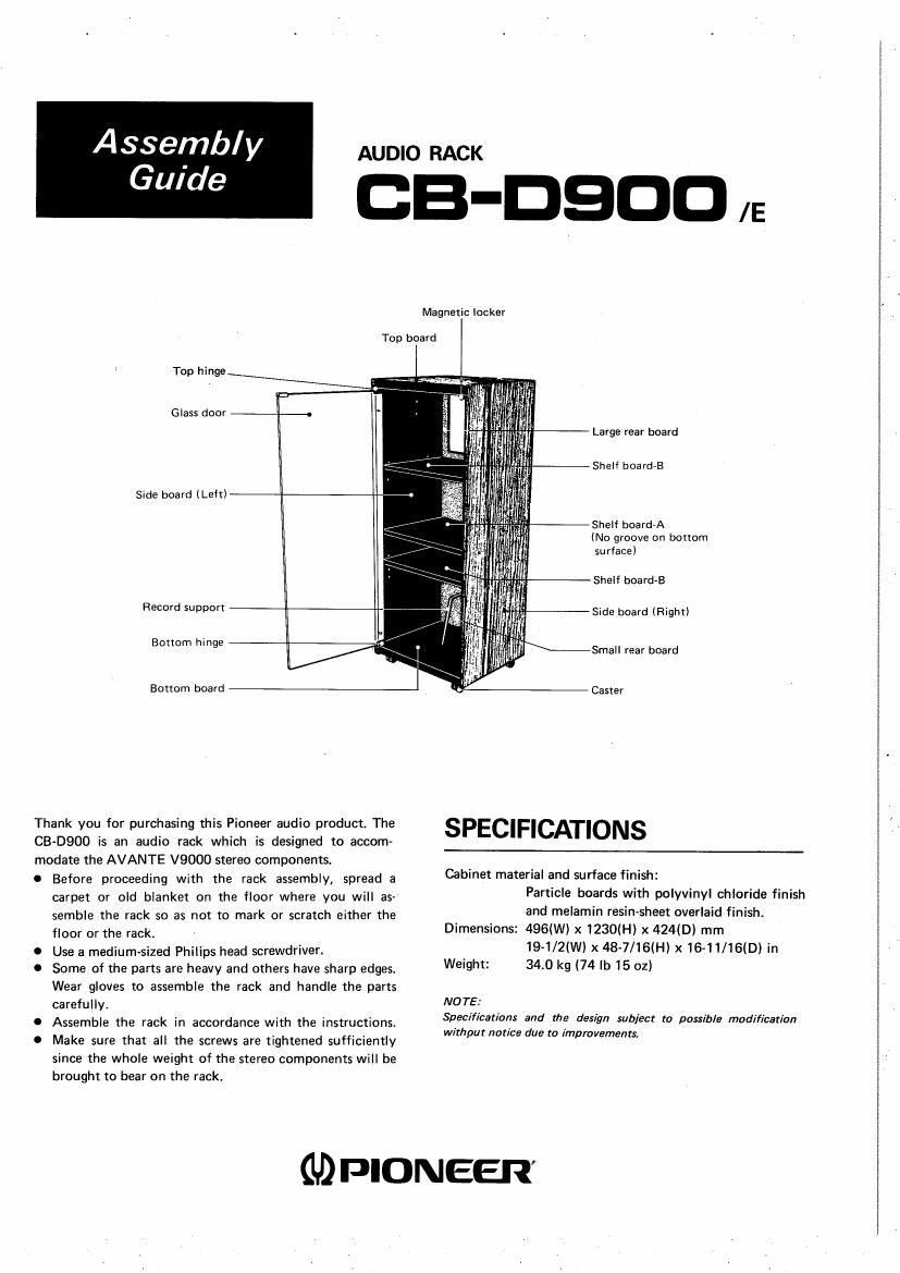
ASSGMb/V AUDIO RACK

Guide CB-DSDD n:

Magnetic locker

Top board

Top hinge

Glass door ._. -

Large rear board

Shelf board-B

Side board l Left)

Shelf board-A
(No groove on bottom
surface)

Shelf board-B

Record support

Side board (Right)

Bottom h'n e
l 9 Small rear board

Bottom board Caster

Thank you for purchasing this Pioneer audio product. The SPECIFICATIONS

CB-D900 is an audio rack which is designed to accom-
modate the AVANTE V9000 stereo components.

0 Before proceeding with the rack assembly, spread a Cabinet material and surface finiShI
carpet or old blanket on the floor where you will as- Particle boards With polyvinyl chloride finish
semble the rack so as not to mark or scratch either the and melamin resinAsheet overlaid finish.
floor or the rack. Dimensions: 496(W) X 723004) X 424(0) mm
0 Use a medium-sized Philips head screwdriver. 19-1/2(W) x 48-7/16lH) x 15-11/16(D) in
0 Some of the parts are heavy and others have sharp edges. Weight: 340 k9 (74 'b 15 02)
Wear gloves to assemble the rack and handle the parts
carefully. NOTE.-

Specificatians and the design subject to possible modification

0 Assemble the rack in accordance with the instructions. _ _
wrrhgur notice due to improvements.

0 Make sure that all the screws are tightened sufficiently
since the whole weight of the stereo components will be
brought to bear on the rack.

GDPIONEER'

Page 2

CHECKING THE PARTS

ASSEMBLY PROCEDURE

The names and quantities of the parts are shown in the
parts list. Check that all the parts are present.

The names and shapes of the parts are required for the
assembly procedure and should thus be remembered,

PARTS LIST

2 MOUNTING THE TOP BOARD, SIDE
BOARD (LEFT), BOTTOM BOARD AND

Part/Application Quantity Physical outline

Cabinet retaining screw/

for fixing the side boards 12
and etc.

Rear board mounting screw/ 18
for fixing the rear boards (1 spare)

Plastic dowel/

boards

Cable clip/
for bundling the power 2
cord and connecting cords

W

em»-

for mounting the shelf 8 0:33
13%

SHELF BOARD-A

Cabinet retaining screw


Top boa rd

Shelf board-A
(No groove on
bottom surface)

Side board (left)

Bottom board

Caster mounting screw/ 13
for fixing the casters (1 spare)

(3 MOUNTING THE SIDE BOARD (RIGHT)

Caster 4

Record support 2

Component stopper/
For safeguarding against
any movement of the

0mm:-

Q}

$4
2 Cy

components housed

ASSEMBLY PROCEDURE

l MOUNTING THE CASTERS

Caster mounting screw

\3
l

Caster
Bottom board

2
*

Cabinet retaining screw

4 MOUNTING THE REAR BOARDS

Place the rack as shown in the diagram on page 3.
First, straighten out the rack and then mount the large rear
board and small rear board.

1. Press the small rear board against the bottom board and
align the side board corners evenly with the rear board.

2. First, fasten the bottom board and small rear board with
screws; then, fasten the side boards and small rear board
screws.

3. Attach the large rear board in the same way as the small
rear board. Attach the cable clip at the position shown
in the diagram.