Pioneer C90 Service Manual

This is the 33 pages manual for Pioneer C90 Service Manual.
Read or download the pdf for free. If you want to contribute, please mail your pdfs to info@audioservicemanuals.com.

Page: 1 / 33
left right
Pioneer C90 Service Manual

Extracted text from Pioneer C90 Service Manual (Ocr-read)


Page 1

«Self/ice

CIRCUIT DESCRIPTIONS

REPAIR & ADJUSTMENTS

STEREO CONTROL AMPLIFIER

04) DIONEER

ORDER NO.
ARP1184-A

O-BOCBKJ

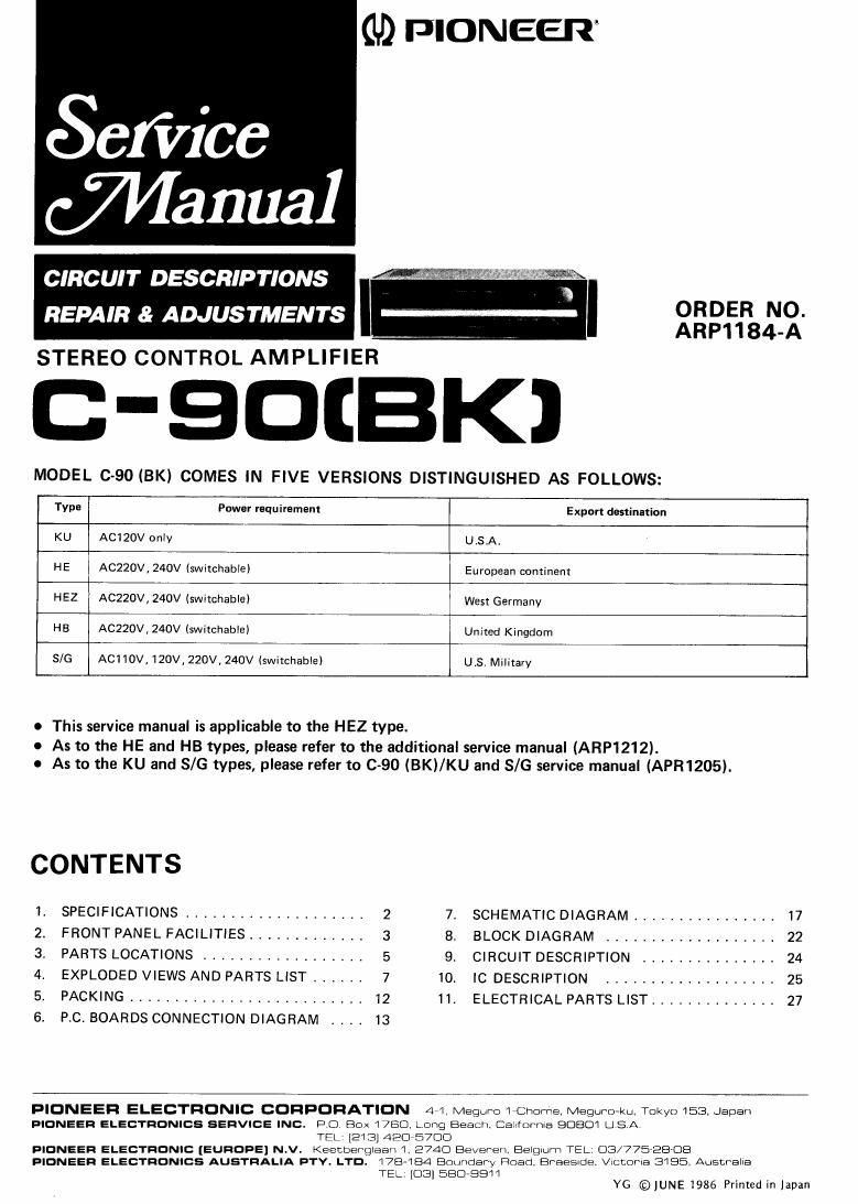
MODEL C-90 (BK) COMES IN FIVE VERSIONS DISTINGUISHED AS FOLLOWS:

Type Power requirement Expert destination
KU ACIZOV only U.S,A.

HE ACZZOV, 240V (switchable) European continent

HEZ AC220V, 240V (switchable) West Germany

HB ACZQOV, 240V (switchabIEI United Kingdom

S/G ACIIOV, 120V, 220V, 240V (switchable) US Military

o This service manual is applicable to the HEZ type.
As to the HE and HB types, please refer to the additional service manual (ARF1212).

0 As to the KU and 8/6 types, please refer to 0-90 (BKI/KU and S/G service manual (APR1205).

CONTENTS

PIS-"3550.?

SPECIFICATIONS ....................
FRONT PANEL FACILITIES .............
PARTS LOCATIONS

EXPLODED VIEWS AND PARTS LIST ,,,,,,
PACKING ..........................
P.C, BOARDS CONNECTION DIAGRAM

SCHEMATIC DIAGRAM ................ 17
BLOCK DIAGRAM ................... 22
CIRCUIT DESCRIPTION ............... 24
IC DESCRIPTION ................... 25
ELECTRICAL PARTS LIST .............. 27

PIONEEFI ELECTRONIC CORPORATION 44 Megurc l Gnome, Meguro-ku. Tokyo 153, Japan
PIONEER ELECTRONICS SERVICE INC. Po. Box 1750 Long Beach. Caninrnla 9080! USA

TEL: [213] 420 570C)

FIDNEEFI ELECTRONIC [EUROPE] N.V. Keecberglaan I. 2740 Bavarian. Balgiurn TEL. US/77528'DE

FIONEER ELECTRONICS AUSTRALIA FTY. LTD.

178484 Boundary Road. BPBBSIde, VICCUIIS 3185. Ausnralia
TEL. [C33] 5EIC3>ESTI

VG ©JUNE1986 Printed in Japan

Page 2

1. SPECIFICATIONS

Amplifier section
Rated power

20Hz-20 kHz, 0.01% .. .................................. 8V
Harmonic distortion

20 Hz-20 kHz, 1 V ........................................ 0.002%
Cross modulation distortion (50 Hz: 7 kHz = 4 : 1)

1 V ............................................................ 0.002%
Input terminals (sensitivity/impedance)

PHONO MM ..2.5mV/50k§2

PHONO MC ..... ....250pV/40S2

125 (JV/3 Q

TUNER, CD, TAPE PLAY, ADAPTOR ....... 150 mV/SO kQ
Output terminals (output level/ output impedance)

TAPE REC .. .. 150 mV/l k9

PHEOUT ...... 1V/600S'2

Frequency response
PHONO MM 20 H2720 kHz ...........
TUNER, CD, AUX, 20 Hz-20 kHz

Tone control


BASS ..... .

TREBLE .. .:9dB, 10 kHz
Filter

LOW (SUBSONIC) .. ...... 7 Hz, 6dB/oct

HIGH 10kHz,6dB/oct
MUTING .. ............... -20 dB
SN ratio (short-Circuit, A network)

PHONO MM .................................................. 96dB

PHONO MC .................................. ....86dB

TUNER, CD, TAPE PLAY, ADAPTOR .. .. 109 dB

Power section, etc.

Power requirements ......................... AC 20 VW. 50/60 Hz
Power consumption ................................... 26 W
AC outlets
Linked to power switch (x2) 250 W
Unlinked to power switch (x1) 250 W
External dimensions 457 (W) x 405 (D) x 125 (H)
Weight ................................................ 9.0 kg
Accessories
Operating Instructions ................................................ 1
Pin-plug cord ........................................................... 1

The specifications and appearance noted above may change
without notice due to improvements.

Precautions for installation

To ensure optimum sound quality, observe the following

precautions.

0 This unit is heavy. Be sure to install it on a firm base which
can support its weight. Also, to prevent the flow of cooling
air from being blocked off, do not place the unit on soft
material such as a carpet or cushion, or install it in a
confined space. When installing the unit in a rack, provide
adequate space around it to allow heat to dissipate.

' To prevent the control amplifier from picking up noise due
to leakage flux from the power amplifier when the control
amplifier and power amplifier are installed adjacent to each
other, install the control amplifier on the right of the power
amplifier. Also, if you install the control amplifier above or
below the power amplifier, place a partition between them
to separate them by at least 10 cm from each other.

- Install the unit on a level surface so that the feet of the unit
are all touching the installation surface.