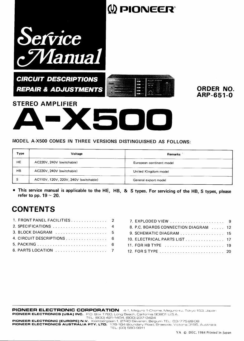
Pioneer ax 500 service manual

This is the 22 pages manual for pioneer ax 500 service manual.
Read or download the pdf for free. If you want to contribute, please mail your pdfs to info@audioservicemanuals.com.

Page: 1 / 22
left right
pioneer ax 500 service manual

Extracted text from pioneer ax 500 service manual (Ocr-read)


Page 1

(I!) PIONEER"

efiice

Wanna]

CIRCUIT DESCRIPTIONS

ORDER NO.
ARP-651-0

REPAIR & ADJUSTMENTS

STEREO AMPLIFIER

A-XEOO

MODEL A-X500 COMES IN THREE VERSIONS DISTINGUISHED AS FOLLOWS:

Type Voltage Remarks '
HE ACZZOV, 240V (switchable) European continent model

HB ACZZOV, 240V (switchable) United Kingdom model

5 A01 10V, 120V, 220V, 240V (switchable) General export model

o This service manual is applicable to the HE, HB, & S types. For servicing of the HB, S types, please
refer to pp. 19 ~ 20.

CONTENTS

I. FRONT PANEL FACILITIES .............. 2 7. EXPLODED VIEW ..................... 9
2, SPECIFICATIONS ..................... 4 8 PC, BOARDS CONNECTION DIAGRAM ..... 12
34 BLOCK DIAGRAM .................... 5 9. SCHEMATIC DIAGRAM ................. 15
4A CIRCUIT DESCRIPTIONS ................ 6 10. ELECTRICAL PARTS LIST ............... I7
5, PACKING ........................... 6 II. FOR HB TYPE ....................... 19
6. PARTS LOCATION .................... 7 12, FOR 3 TYPE ........................ 20

PIONEER ELECTRONIC CORPORATION 44 Megurcz mahome Megumrku Tokyo 15:3 Japan
PIONEER ELECTRONICS [USA] INC. P O Box 1750, Long Beach Csiirumua $30801 u S A
TEL. [800142171404 [BOD] 237-0424
PIONEER ELECTRONIC [EunOpE] N.v. Kentmergiaan I 2740 Bevereix BeIquI'ri TEL 05/775 28 DB
DIONEEn ELECTRONICS AUSTRALIA DTY. LTD. 178 184 BOLI'TdaIy moan Bhaesde, chcma £3195 Allscmia
TEL [mm 5F?O«EQII

YA © DEC. 1984 Printed in Japan

Page 2

1. FRONT PANEL FACILITIES

O s 5

42s;

L GET T L a 2

1.2....- V .L
EImVfi'f-Lyin

@®@

6) POWER switch

Press to turn power to the unit 0N and OFF.
Depressed position (0N):

Power is supplied to the unit.

Released position (OFF):

Power to the unit is disconnected.

@ FUNCTION switches/indicators

lPl-lONO] ~ Press when listening to record playback
on a turntable.

[TUNER] 7 Press when listening to AM or FM broad-
casts with a tuner.

[CD/VIDEO] 7 Press when listening to programs
from a component connected to the CD/VlDEO
terminals.

[TAPE 1] - Press when listening to tape playback
with a tape deck.

ITAPE 2/ADAPTORJ - Press when using a compo-
nent (sound processor, graphic equalizer) connected
to the TAPE 2/ADAPTOR terminals. Also can be used
during tape playback when a tape deck is connected to
these terminals.

NOTE:

When a component is not connected to the TAPE Z/ADAPT
TOR terminals, or when the component connected is not be
ing used, be sure to set the { TAPE 2/ADAPTORI switch to
the OFF position (the indicator will go out). If set to the ON
position, no sound will be heard.

© LOU DNESS switch/indicator

Use when listening at low volume levels,
Low and high frequencies are boosted to give punch
to playback, even at low volumes.

(4) BALANCE control

Should normally be left in the center position. Adjust
balance if the sound is louder from one of the
speakers. If the right side is louder, {turn toward the
(L) position and if the left side is louder, turn toward
the (R) position.

® VOLUME control

Use to adjust volume level.
Move up to increase volume.
Move down to lower volume.

@ PHONES jack

When using headphones, insert their plug into this
jack. The sound from the speakers will automatically
be disconnected,

® MIC jack
When using a microphone, insert its plug into this
jack,