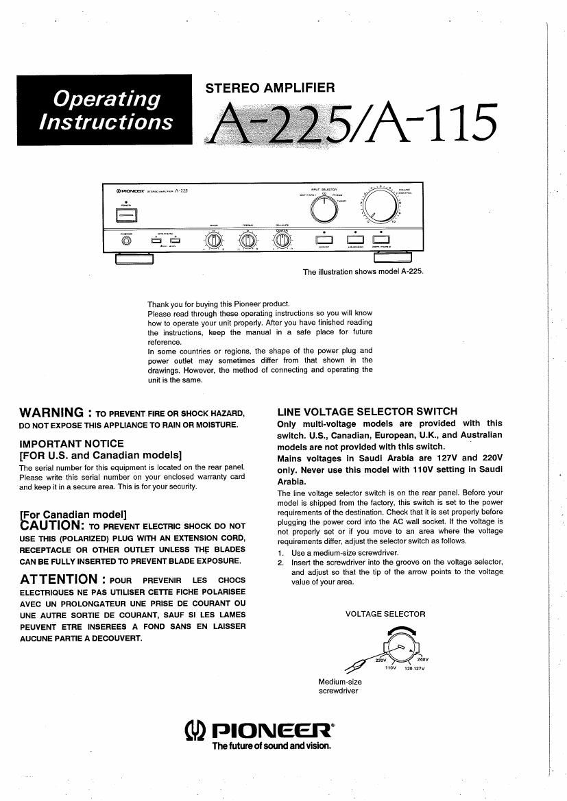
Pioneer a 225 owners manual

This is the 12 pages manual for pioneer a 225 owners manual.
Read or download the pdf for free. If you want to contribute, please mail your pdfs to info@audioservicemanuals.com.

Page: 1 / 12
left right
pioneer a 225 owners manual

Extracted text from pioneer a 225 owners manual (Ocr-read)


Page 1

. STEREO AMPLIFIER
Operating

lnstruc tions


damn-saw ,.m.m.:.. A-zzs

The illustration shows model A-225.

Thank you for buying this Pioneer product

Please read through these operating instructions so you will know
how to operate your unit properly. After you have finished reading
the instructions. keep the manual in a safe place for future
reference.

In some countries or regions. the shape of the power plug and
power outlet may sometimes differ from that shown in the
drawings. However. the method of connecting and operating the

unit is the same.

WARNING : To PREVENT FIRE OR SHOCK HAZARD,
Do NOT EXPOSE THIS APPLIANCE To RAIN DR MOISTURE.

IMPORTANT NOTICE
[FOR US. and Canadian models]

The serial number for this equipment is located on the rear panel.
Please write this serial number on your enclosed warranty card
and keep it in a secure area. This is for your security.

For Canadian model]

EAUTION: To PREVENT ELEcTRIc SHOCK DO NOT
usE THIS (POLARIZED) PLUG WITH AN EXTENSION cORD,
RECEPTAcLE on OTHER OUTLET UNLEss THE BLADEs
CAN BE FULLY INSERTED TO PREVENT BLADE EXPOSURE.

ATTENTION 2 POUR PREVENIR LEs CHOCS
ELEcTRiOUEs NE PAs UTILISER CETI'E FICHE POLARISEE
AVEc UN PROLONGATEUR UNE PRISE DE COURANT ou
UNE AUTRE SORTIE DE COURANT, SAUF sI LES LAMEs
PEUVENT ETRE INSEREES A FOND sANs EN LAISSEFI
AUCUNE PARnE A DECOUVERT.

LINE VOLTAGE SELECTOR SWITCH

Only multl-voltage models are provided with this

switch. U.S., Canadian, European, U.K., and Australian

models are not provided with this switch. 4

Mains voltages In Saudi Arabia are 127V and 220V

only. Never use this model with 110V setting in Saudl

Arabia.

The line voltage selector switch is on the rear panel. Before your

model is shipped from the factory. this switch is set to the power

requirements of the destination. Check that it is set properly before

plugging the power cord into the AC wall socket. If the voltage is

not properly set or if you move to an area where the voltage

requirements differ, adjust the selector switch as follows.

1. Use a medium-size screwdriver.

2, Insert the screwdriver into the groove on the voltage selector,
and adjust so that the tip of the arrow points to the voltage
value of your area.

VOLTAGE SELECTOR

A

240v
Nov immv

M ediu m »s ize
screwd river

(U) PIONEER

The future ofsound and vision.

Page 2

IM PO RTANT 1

The lightning ilash with arrowhead. within an
equilateral triangle is-inlended to alert the user or the
presence 01 uninsulated dangerous voltage" within the
product's enclosure that may be or surlicient magni-
tude to constitute a risk or electric shock to persons

CAUTION

RI OF ELECTRIC SHOCK

DO NOT OPEN

CAUTION:

TO PREVENT THE RISK OF ELECTRIC SHOCK. DO NOT
REMOVE COVER (OR BACK). NO USER-SERVICEABLE
PARTS INSIDE. REFER SERVICING TO QUALIFIED
SERVICE PERSONNEL.

The exclamation point within an equilateral triangle is
intended to alert the user of the presence oi important
operating and maintenance iservicingl instru
the literature accompanying the appliance.

IM PORTANT 2

II the apparatus is titted with AC mains power out-
letts). see REAR PANEL FACILITIES lor convenient
connection OI addltional Hi-Fi componentls). Make
all connectlons to the AC outlet(s) and the signal
terminals lirsr. Connect the plug to the wall socket
last, make sure that the power switch is all

FOR USE IN THE UNITED
KINGDOM

The wires in this mains lead are coloured in accor-
dance with the lollowing code:

Blue: Neutral

Brown: Live

As the colours DI the wires in the mains lead OI this
apparatus may not correspond with the coloured
marking identiiying the terminals in your plug proceed
as follows.

The Wire which ls coloured blue must be connected to
the terminal which is marked With the letter N or
coloured black.

The wire which is coloured hrown must be connected
to the terminal which is marked with the letter L or
coloured red

Equipment sold in the UK. is nut supplied with
a power plug.

SAFETY INSTRUCTIONS

READINSTRUCTIONS e Allthe salary and operairng
instructions should be read before the appliance
is operated.

RETAIN INSTRUCTIONS -~ The operating instructions
should be retained for future reference.

HEED WARNING 7 All warnings on the appliance and
in the operating instructions should be adhered to.

FOLLOW INSTRUCTIONS - All operating and usei .
structions should be Inllowed.

WATER AND MOISTURE - The appliance should not
be used near water .7 lar example, near a bathtub.
washbawl, kitchen sink, laundry tub, in a wet
basement, or near a swimming pool. etc.

LOCATION - The appliance should be installed in a
stable location

WALL OR CEILING MOUNTING 7 The appliance
should not be mounted to a wall or ceiling.

VENTILATION - The appliance should be situated so
that its location or pusilion does not lnterIere with
its proper ventilation For example, the appliance
should not be situated on a bed, sota, rug, or simi-
lar surface that may block the ventilation openr
lngs', or, placed in a built-in installation. such as
a bookcase or cabinet that may impede the Ilow
oi air through the ventilation openings.

HEAT 7 The appliance should be situated away from
heat sources such as radiators, heat registers.
stoves. or other appliances (including amplifiers!
that produce heat.

POWER SOURCES - The appliance should be curl-
nected to a power supply only or the type
described in the operating instructions or as
marked on the appliance.

POWER-CORD PROTECTION - Power-supply cards
should be routed so that they are not likely to be
walked on or pinched by items placed upon or
against them, paying particular attention to cords
at plugs, convenience receptacles. and the point
where they exit from the appliance.

POLARIZATION --- ll yuur purchased product is provid-
ed with a polarized power plug, please read the Iolv
lowing instructions. This product is equipped with
a polarized alternating current line plug [a plug hav-
ing one blade wider than the oiherl. This plug will
Iil lnto the power outlet only one way. This is a
salety feature. ll you are unable to insert the plug
lully into the outlet, iry reversing the plug. lithe
plug should still tail to lit, contact your electrician
to replace your obsolete outlet. no not deleat the
safety purpose or the polarized plug.

CLEANING - The appliance should be cleaned only
with a polishing cloth or a soft dry cloth. Never
clean with furniture Wax, benzine, insecticides or

POWER LINES - An .outdoor antenna should be
located away lrorn power lines

NONUSE PERIODS- The power cord of the appliance
should be unplugged irom the outlet when lalt
unused lor a long period or time

OBJECTAND LloulD ENTRY - Care should be taken
so that objects do not lall and liquids are not spilled
into the enclosure through openings.

DAMAGE REQUIRING SERVICE - The appliance

should be serviced by a Pioneer authorized service

center or oualllied service personnel when.

The power-supply cord or the plug has been

damaged; or

Objects have lallen, or liquid has been spilled into

the appliance: or

The appliance has been exposed to rain, or

The appliance does not appear to operate normally

or exhibits a marked change in perlormance; or

The appliance has been dropped; or the enclosure

damaged.

SERVICING - The user should not attempt to service
the appliance beyond that described in the oper-
atinginsiruciions. Forallother servicing. contact
the nearest Pioneer aulharlzed service center.

.0...

POWER LINES

SERVICE
ENTRANCE
CONDUCTORSv

- TERMINALS 0F


OUTDOOR ANTENNA GROUNDING - ll an outside

antenna is connected to the antenna terminal. be
sure the antenna system is grounded so as to pro-
vide some protection against voltage surges and
built up static charges.
In the U.S.A. section 810 of the National Electri-
cal Code, ANSI/NFPA No 70-1984, provides
information With respect to proper grounding col
the mast and supporting structure, grounding ot
the lead-in wire to an antenna discharge unit. size
or ground g conductors, location or antenna dis-
charge unit, connection to grounding electrodes,
and requirements tor the grounding electrode. See
Fig. A.

CART - An appliance and call combination should be
moved with care. Quick stops. excessive force,
and uneven surlaces may cause the appllance and
cart Combination to overturn.


v

al Use No.10 AWG 45.3mm sour
per, No a AWG (8.4 mrnii aluml-
num, No. l 7 AWG ll .0 mml
capperaclad steel, bronze wire, or
larger as ground wire.

bl Secure antenna lead-in and
ground wires to house with stand-

SWD-OFF ori insulators spaced ham 4 leer

'NSULATORS (LZZ nietersl to s Ieet it .83
. meters) BDBFI.

fggmc c) Mount antenna discharge unit as

WIRE closely as possible io where lead

In eniers house.
Use ,umoer wire not smaller inan
No.6 AWG (13.3 rnm-l copper, or

To EXTERNAL d)
ANTENNA

PRODUCT the equivalent, when a separate
GROUND antenna-grounding electrode ls
WIRE ,b ANTENNA
GROUND a - DISCHARGE gseimc s . 81° 21 .
SERVICE ENTRANCE CLAMPS umt c 88 ectlnn - lllr
EQUIPMENT GROUND
wrne a.b
GROUND
POWER SERVICE - CLAMPS
GROUNDING ELECTRODE svstEM
le 9. Interior metal wale- pipel OPTIONAL ANTENNA


GhOUNDlNG ELECTRODE

other volatile liouids since they may corrode the gamma ii.- DRWEN a FEE, ,1 M m,
cabinet. JUMPER fl INTO TNE EARTH
FIG A IF REQUIRED BY
' LOCAL CODES SEE
NEC SECTION BIG-II lll.
(ARBI 161 >

E