Philips v 7 u service manual

This is the 3 pages manual for philips v 7 u service manual.
Read or download the pdf for free. If you want to contribute, please mail your pdfs to info@audioservicemanuals.com.

Page: 1 / 3
left right
philips v 7 u service manual

Extracted text from philips v 7 u service manual (Ocr-read)


Page 1

VI (Supplement)

'TRADER ' SERVICE SHEET

326

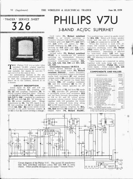
HF. Philips V7U is a 4-valve (plus

I rectifier) AC/DC 3-band supcl'hct

with a short-wave range of i6-

and suitable ior mains of

(40-100 C/S in the case of AC).

An outstanding ieature is the un-

conventional form oi construction used

in that the components are mounted

direct on to the cabinet, instead oi on
a chassis,

CIRCUIT DESCRIPTION

Aerial input on MW and LVV via
isolating condenser 01, coupling «oils
L2, L3 and coupling condenser 04, to
mixed coupled bandpass filter. Primary
coils L4, L5 are tuned by C30 ; secondaries
L10, L11 by C32 ; coupling by condensers
06, C7 and COIlS L6, L7. Ili filtering by
L1, CS across coupling coils. Image
suppression by 05, On SW, input is via
01 and coupling coil L8 to single-timed
circuit L9, 032. R1 across aerial circuit
provides a DC path between sockets A
undE so that Cl cannot develop a charge. '.

THE WIRELESS & ELECTRICAL TRADER

June 18, 1938

PHILIPS V7U

3-BAN D AC/DC SU PERH ET

lviist valve (V1, Mullard metallised
:60130) is an octode operating as
requency changer uith electron coupling
Usullator grid cells L12 (SW), L13 (M\\)
.ind L14 (1.) are tuned by 033;
naniilel trimming by (:34 (LWM series
1.13Lklng by (:14 (MW, anti 013 (UV).
Reaction by coils L15 (SW), L16 (MW)
.inil L17 (LW).

Second valve (V2, Mullard metallised
'VP13C) is ii. variablermu RF pcntode
operating as intermediate frequency
amplifier with tuned-primary tuned-
:-econdary transiormer couplings C35,
011. L18, L19, 012, 036 and 017, L20.
L21, 018.

Intermediate frequency 128 KO/S.

Diode second detector is part 01
«louhle diode trlode valve (V3, Mullafll
metallisei'l TDD130). Audio frequency
component in rec tilled output is developed
lcross load resistance 3.7 And lnanual
volume control RB, which also forms part
of the load, and passed via hxed tone
corrector 020, AF coupling condenser
13531 and CG resistance 13.9 to CG of
liriodo section, which operates as AF
:iinplificr.

Second diode of V3, fed from V2 anode
.lil 022, provides DC potential which
is developed across load resistance 313
.iin fed back through decoupling Circuit
:15 GB to 13C and 11 valves, giving
automatic volume controll Delay voltage.
:ogcther with GB potential for triode
section, is obtained from drop along
33.17 in HT negative lead to chassis.

Rcsistziricencapacity coupling by 311,
i324, 13.14 between V3 triode and pcntodc
output valve (V4, Mallard Pen330).

Two position tone control in anode circuit
by $14, 026. Metal grill frame, speaker
[mine and one side of speaker Speech
coil L23, iire connected to socket E.

hen the receiver is used With AC
mains, HT current is supplied by IHI
halt-wave rectifying valve (V5, Philips
CYIC) which, on DC mains, behaves as ii
low resistance. Smoothing is effected
Ivy iro -cnred choke L22 and large
capacity wet electrolytic condensers 025,
027. RF filtering in rectifier anode circuit
by C28.

Valve heaters lire connected in series,
together with scale lump and current
regulating barretter (Philips 01), across
mains input. Filter chokes L24, L25
suppress mains-borne interference.

COMPONENTS AND VALUES

RESISTANCES
Aerial Circuit Safely shunt . .
R: Vr pentolle CG decoupling ..
R3 Vr pentode grid stabiliser .. l 50
V1 osu. CG mistance
Osc circuit sw stabiliser


V1, V2 so 5 and vi 05c anode i
in Iced (approx. ., l x9,5oo
R7 : 11m v3 Signal diod 031200000
RE : Manila] voluniewiitrol' par-t
V3 signal diode load 5m ooo
no V31iinde u; resistance l lion 000
km : V3 (node cc decoupling . 250 000
RH . v; mode anode Iorid . 3213000
R12 l AVCline decoupling H . 1,000,000
Rig . Vi AVC diode 10.141 500.000
Ru . V; CG resistance 800.000
Rls , vi gn'il shopper 200,000
R16 1 V4 GB resistance 1 [8o
R17 V3 triode GE and AVC delay
(approx) . .. l 30f
Rifi V5 anode cnmni liniitor .. ; 115

- 'luo m 000 o and one so om o in parallel.
1 One :25 o and one 40 o in parallel.

XS
L10 LII
A CH 'é-
\-4
V15
fi' is
" 5 6
L8
5! C4
n U C19
1
ll U C5 Cigfl
I U is
3) 34
ca: I
C27
) L6 .:WE7 R1 ILIO CISII Clb .
.. C7
1' L 1 '
. l . l . - /
leCLul diagram of the Philips V7U. The second IF transformer A: Dr
may have semi-fixed trimmers across 017 and 018 in some SCMEWmmm m Mm?
chassis. Other ssible diver encias are under General Notes. V3 V4 V1 VI .
.. p0 g L15 575$

I
a

Page 2

June 18, 1938

s v l Values

THE WIRELESS &

COhDEhsnRS (Fl
Cr i Aerial isolating condenser .. o-oo5
c: Earth isolating condenser . . onus
C3 l Aerial IF filter tuning o-oootir)
C4, i Aerial MW and LW coupling o-ooooz
C5 1 iii/iii suppressor . . i oroomi
C6 and pass mupling Mira
C7 lilw band- -pass coupling i noes
C5 1 Aerial 5W trimmer . . l u-oooox
Cg i Small coupling . .l o-oooooz
Cxc . \ r healer RF by- pass l o-or
Cu 15: IF trans. pri. fixed trimmer o-ooolsi
C12 rs: IF Inns. sec. fixed trimmer o-ooorés
CI] 054: circuit LW tracker i i 0-0007
Cu 05¢ circuit MW tracker . (roomy
C15 Vr, V2 SGs and V1 use. anode
, 1 decoupling .. .. .. . ii-r
C15 V2 CG decoupling . i . , o-l
C17 and IF transt nri. tuning 0 cool 55
Cifi 2nd IF tranx sec. inning n inning
C19 . niuphiig to V3 signal dioili- noonoxt)
C20 ll'lxerl tone mneclm- . . a (10!
C2: A1: conpllng in V3 tmido u or
(:22 Coupling l0 \3 Ave diode otooooobs
ng V3 triotte CG LlConllpllng 0 25
C25 V3 triodc to V; AF coupling u or
(125* , Part HT mouthing
C26 . Tone Conuol cunllenser
Cz7 Pnrt HTsm olhiltg
C25 V5 amid R by~paasu
Cry: Band. s ini. MW tilniiiiei o-iiunins
Cgut Band-pass primary inning . . o-nnnin
c 3r; mini pass 3e42MVV1llmmt-l _ l
cgzi Acriil SW and hand piss ,

. set: tuning . , ii 000m
C331 Oscillator u- rniit tuning .V l (mom
034: l Oso. circuit 1w trimmer . o-uooo;
535: rst lIi trans. pri. tuning u-oooo;
C36: rst 1F mus. sec. tuning . . 0-0000]

' Electwlytic. 1 Variable. : Preset.

CONNECTION

Rear view of the receiver, which
has no removable chassis. The two
switch units are shown in detail on
page vrll. C34, 035 and 038 are
semi-fixed trimmers.

Annrox.

ELECTRICAL TR ADER

orllm coleoerTs . Values
l (iihiiis)
Lr . AuizllF fillereoil l 1300
L2 }A(nal Mw and LW . l .5 n
L3 coupling mils i. i l 90 n
L . , .
L; lyBAIldrPISS pnmar} coils l l g:
11:: . . [hind-pass coupling cnils l 3;?
L8 Ae n1 sw cvuphni: Coll 2 0
Ln Aernil sw tuning coll.. i u 2
B: 1 nnnitpnss secondary mils { 42::
LXI osu (uCulL 5w tuning cull . . . u-2
Lig clrcttit \lW inning nini .. . ion
L11 rirruit l.w tuning tuil .. is ii
1J5 Usrillntnr 5w rmelrnn . l :5 ii
Lin osrillntor nw reactlml n 05
Li7 UsClllntor Lw leacllor. i. 5
. i . r In rum
.in If tiiins. _ 5 > , W
. _ , lrl . , lilo n
and ii" Iran. 5 _ l m
T smoothing (halls . ino ii
Speaker speech ml ,. . i m
Mains RF hltor Chaim, l! 2
i Pri. 304) 0
Output trans Sec _ W

Waie'band switches
Tune coulml swltch .
\lalns switches, ganged RE -A

(Supplement) VII

DISMANTLING THE SET

It is not possible to remove the receiver
from the cabinet as a whole but there are
Various sub-assemblies which can be
taken out as complete units, if necessary.
Sornc of the components are held in
place with pitch and a similar material
will have to he used for my xlng them.

Removing Sunkenilf it is desired to
remove the speaker {mm the cabinet.
unnoltler the speech cull leads (taking ii
calellll note of the points to which they
are connected) and then remove the
{our screws (\rlth washers). one at each
comer of the speaker moulding. The
grille covering the speaker aperture can
thon be removal, exposing the heads of
{our holrn (with nuts 11ml lock nuts)
whlch hold thr- spenkcr to the cabinet.
These should he removed. when the
speaker can he \i'lthrlmwn from the front
of the cabinet.

lV/n-ii ryplut'ing, inikt- sure, that tht-
thlee Ltlrtlllllg tags are secured by the
:tpllropilllte hXIllL screws.

VALVE ANALYSIS

\"lllvc voltages (mil currcnts glVfll in
the table (p. VIII) are those monsurt-(l in
mi receiver when it was operating (in AC
mains of 230 The recelver was tuned
to the lowest wavelength on the medium
band and the volume control was at

Continued overleaf