Philips v 5 service manual

This is the 2 pages manual for philips v 5 service manual.
Read or download the pdf for free. If you want to contribute, please mail your pdfs to info@audioservicemanuals.com.

Page: 1 / 2
left right
philips v 5 service manual

Extracted text from philips v 5 service manual (Ocr-read)


Page 1

16

IllcUIT.-A bandpass input circuit
couples the aerial to V1, the he
quency changer. The aerial is con-

nected through it series condenser on long
and medium waves and direct coupled on
the short wnveband,

Coupling to V2, on HF. peniode, is an
I.l<, transformer tuned to 128 kc. A
second LF. transformer feeds the signal
to V5, :1 double diode triode.

(hie diode of V5 is used for demodula-
limi Lind the other, which is coupled to
V2 by (.25, supplies A.\/.C, bids, which is
in] to the preceding valves.

The output of the demodulator diode is
lthlniflill? and capacity coupled to the
tt'iodc s [10]] of V5. the network includ-

l

05C;

COILS
L

WC

F

_ L512 CM-

CIS

BPAE
COILS

Broadcaster Service Mans Manual

PHILIPS V5
A.C. SUPERHET

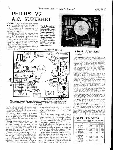
One of the most urt-
orthodox receivers
introduced tor many
years, the model V5
by Philips Lamps Ltd.
has no chassis in the
usual sense. As this
picture shows the set
comprises a. numhar
of sub-assemblies
mounted direct on
the inside of the
moulded cabinet.

OUTPUT TRANS

(:5 l\


AECOILS v5

R7 (VOLUME CONTROL)

This diagram presents the same View as the above photograph and enables all the

parts to be identified.

Reference is aided by all resistances being indicated in

solid black.

ing the volume control. A further resist-
ance and capacity stage connects the out-
put peniode, V4, which drives the perina-
nent-utsgnet speaker.

Mains equipment consists of Ct trans
former and half wave rectifier. Smoothing
is by a, resistance, R], in the negative
return lead and the. usual electrolytic Coir
densers.

Special Notes-The dial light is the
usual Philips type 8042. The holder will
be found screwed to the hose of the
cabinet behind the voltage adjustment
panel The best way to remove it is to
take out the rectifier, and then reach in
and unscrew it from its holder.

Connections are provided for a gramo-
phone pick-up. These are taken to the
grid 01' V3 through the volume control.
No switching position is provided, how
ever. the connection of a pickup being
sufficient to render the diode inoperative

This receiver does not employ a chassis

in the usual sense of the word, the assem-
bly Hiking the form of separate units
bolted to the sides and front. of the
cabinet.

For all the usual 5e 'tcc work there, is
no need to remove any of the 9, units, the
components being fully acce ihle, more so
than in the majority of orthodox chassis.
The coils are fixed into slots by pitch.

Switching ExplanationiAs shown in
the circuit diagram, the switches are in
the short, wave position. They Work in it
clockwise direction, the order of operation
being short, medium, long waves. There
is no gi'mmophone switch position.

Small circles represent contact springs
and the short radial lines indicate short-
ing contacts on the rotor. These rotor
contacts may be connected together, in
which case solid arc lines are shown, or
may link at number of stator contacts, in
which case dotted " arcs are given.

Circuit Alignment
Notes

I.F. circui

,-T(cl'crcnn- to the circuit dia-
trrnni \ ow ltlmt tlic ltlvV trllnaiormors used
in this I'vun ' have fixed trimming (:(tntllllielh.
It is unlikely that 1|(lil Uncut will become
ncccs iy, but in this 1' t the self inductance
lit-tween tho Ll. co used for trimming.

Etull Pull it out oi two cm]:
When the tli the sail iiiillltlflllict, is nitcreil d consequently
the intermediate frequency, The outer Coils:
only ~lionld be altered, in ii' the inner (oils
are {idjnstcd in our why the blind-width is
L'ilttl'ltl Consillcrnblv.

The small coils (in the tube are Fixed in
position by moon, of mix mutt they must be
rclcusi-d hr moons of It warm soldering iron.
Adjustments mtiy he led out by hand, pro»
\llllllg u rubber glovo . worn.

Win-u it is nccc. l to alter the coils, rziro
should lite taken to nmltc sure that the wires
do tint brthk. If it is found that one M the
coils should bmomc nvpcll t'lrcuilod, talk-n it is
d. blc tn Tcfit :1 new call assembly. When
tli bell! done it. is important to one thnt
they . c wrrectlr ninrotl in position, "5 other»
wise it Will be fountl that tho hand-width is too
narrow (Ind the volume Insnlficit-nt.

(112 consists of ti thick wt : with a thin in:
wound on it. null this assembly is fixed with
wax.

Wlicii trimming [le0 volume (nntml must be
placed at maximum and it is important tlint
both the rcccivcr and service oscillator should
be correctly earthen.

(i) Inject a modulatcd 128 kc. signal to the
grid of V2 through rt 52,000 mmfd. condenser.
First adjust the outer coil of L175, and after that
the outer coil of L22.

(2) Apply a modulated signal of 128 hr. via a
condenser of 32,000 mmftl. to the fourth grid
of VI, Adjust the Inlte/I coils 01 L20 and L21.

(4) Apply a modulated signal of 12.8 kc. to
the ucriat socket Via a condenser of 140 mrmtri.
Adjust the receiver to long waves and tune the
variable cmulcnscr to its, maximum capactty
(2.ll00 metres). Heat L5 and trim until the

No signal. Volume maximum. 200 volt AI.
mains.
v. pe. Electrode. Volts. Mi.
1 FC4 met. Anode .. 245 1.7
(7) Screen .. 85 1.9
Mullard Osmanode 85 3.3
2 VP-iB met. Anode .. 17" 5.75
(7) Screen .. 170 1.75
Mullard
3 TDDiilmt. Anode 7F .47
(7)
Mullard.
4 Pen A4 .. Anode .. 260 3
(7) Screen .. 240 4.4
Mllllttfli.
5 1821(4) Filament 260 --
Philly.

Page 2

April, 1937

output indicator indicates :1 minimum \ulllc.

Medium Niven-(1) Adjust the receiver to
medium wuvebnlid and 200 metres.

(2) Rotate 'll completely zllld T2 uppmxi~
mnwly halL

(3) Alpply a mmlulaied signal of 1450 kc. iii;
.1 condenser 01 140 111mm. to the aerial 501' ket.
Rotate the tuning condense-1' slightly until illl:
first signal becomes audible from the. minimum
position and adjust to largest ouilplIL

(4) All ust T2 and T1 until the output indi-
mum in ieales the maximum output.

Long wash-11) Leave l1ihe 111 ng CDmlClNcl'
at its previnus position and adjust lilo: recencr
for reception of long waves

(2) Adjust the service oscillator in 4.11 kc
'llld atljllst 012 In maximum oultpui. If the
capacity should be found to be 410 =mall an
entirely neu lliin wire can be wound on lll(
thicker WirL'.

Broadcaster Service Mans Manual

.l
10000.3

1 7 Band-pass coupling

in Osclllumr cullilol .000002
10 V1 050. grid .. 1. .0007
20 v1 nsn.g1i.l 1. .. .00110
21 in 1 inning 1. .. .. 10mm
22 in l tuning .. 1 . .lmonz
23 [FT 2 Illnlmz . . .00018
24 1F'1' 2 tuning .. .. 1000111
25 A1V.U. diode coupling .000002

211 L1F1uoupli11¢ .1 .. .. .01

27 1-1.F. liy-pasn 1. .. 1001

211 H1F1 bypass .. .. 11011011:

20 111. collplim: .1 01

33 vzr anode nun xcreen «lecoulr
In! .

Purpose. mu;

1 g}: smuolginu . 1 1 . 33

2 smooi. ing 1. .. .1

:1 v1 healer by- pans .. .01

1 \ 1 screen and 051:1 anutle de- RESISTANCES

coupling Purpose. Ohms.

:1 A. V l: decoupling -.___,, V7-
11 V 3 grid ilemupliin: 1 H. 'r. smoothing «1
13 Input shunt circuit (pan) 2 H1 1 decoupling . 1,0110
14 Series aerial 3 V1 and 2 11. '1'. llecolxplin" .. 10,000
1:. V1 A V. C. decoupling 4 V1 A.V .(lecoupling 1 mg
11; Blind-unis coupling 5

V1 use. 1.30119 decoupling 1. 10
6 V1 05c. grid leak . .
7 Volume control
:4 V3 grid leak . 1
9 V3 Krlll hills decoupling
10 A v. C lleconplin" .
11 A.V.(1. diode load
12 V3 anode load
13 V4 grill leak
14 v4 grill stopper
15 V4 cathode MES
16 Demodulatur diode load

17 V1 grid stabilise! . . 50
21 v1 screen null 050. anode (18 10,000
coupling: and 15,400
in series.

17'

Philips V5
on Test

ODEL V5.-Standard model
for 100-280 volt 50100 cycle
A.C. mains. 8 gns.

DESCRIPTION. -A three- waveband
four- valve, plus rectifier, A.C1
super-hat table- type receiver

FEATURES. -Wulnut- tinted bake-
lite cabinet. Large full Vision

station, calibrated dial. Chassis«
less constructmn. Pick-up con<
mention.

Lemma-74 watts.

Sensitivity and Selectivity

Sliom WAVES (17-50 metres}.-
Gain good and no appreciable fre-
quency drift Under suitable con-
ditions 11 number of programmes
should be received.

MEDIUM WAVES (1801600 metres).-
All usual stations obtainable at ex-
cellent slrcngth in davlight. Selec-
rivity is such that there is 11111}!
appreciable overlap 011 the local
transmissions.

LONG WAVES (6502100 metres). -
Good performunue comparable to
that on medium waves. Deutsch-
landsender receivable 1'11 swamp
area with only slight nverlap.

Acoustic Output

Tone is fairly well balanced the
upper frequencies do not predomi-
mate and coloration on speech is
very slight.

Background and hum low.

WY

,ch

2

11 *-_'r-
L_ _ .__l iii: ________ __ _

V5

On the whole the circuit of the V5 (allows the lines of any similar set constmeted on orthodox lines.
however, are trimmed not by capacity but inductance.

R6

1511.

The IJ. translormers,

The switch diagrams are explained on the opposite page.

______.._..._._.__.

.__J

A2