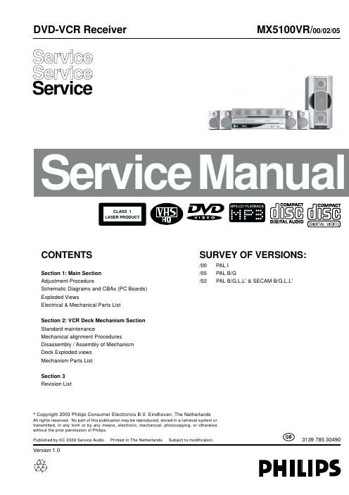
Philips mx 5100 vr service manual

This is the 151 pages manual for philips mx 5100 vr service manual.
Read or download the pdf for free. If you want to contribute, please mail your pdfs to info@audioservicemanuals.com.

Page: 1 / 151
left right
philips mx 5100 vr service manual

Extracted text from philips mx 5100 vr service manual (Ocr-read)


Page 1

DVD-VCR Receiver MX5100VR/00/02/05

Service
Service
Sewice


- COMPACT COMPACT
CLAss 1 H§@
LASER PRODUCT

mm mm DIGITAL VlDEU

CONTENTS SURVEY OF VERSIONS:

/00 PAL |
Section 1: Main Section /05 PAL B/G
Adjustment Procedure /02 PAL B/G,L,L & SECAM B/G,L,L'

Schematic Diagrams and CBAs (PC Boards)
Exploded Views
Electrical & Mechanical Parts List

Section 2: VCR Deck Mechanism Section
Standard maintenance

Mechanical alignment Procedures
Disassembly / Assembly of Mechanism
Deck Exploded views

Mechanism Parts List

Section 3
Revision List

9 Copyright 2003 Philips Consumer Electronics B.V. Eindhoven, The Netherlands
All rights reserved. No part of this publication may be reproduced, stored in a retrieval system or
transmitted, in any form or by any means, electronic, mechanical, photocopying, or otherwise
without the prior permission of Philips.

Published by KC 0339 Service Audio Printed in The Netherlands Subject to modification 3139 785 30490

Version 1.0

@ PHILIPS

Page 2

MAIN SECTION

DIGITAL VIDEO DISC PLAYER,
VIDEO CASSETTE RECORDER &
FM/MW RADIO TUNER

Sec. 1: Main Section

0 Adjustment Procedures

0 Schematic Diagrams and CBAs

0 Exploded Views

0 Mechanical and Electrical Parts List

TABLE OF CONTENTS
LASER BEAM SAFETY PRECAUTIONS ..................................................... 1-1-1
IMPORTANT SAFETY PRECAUTIONS ...................................................... 1»2-1
STANDARD NOTES FOR SERVICING ....................................................... 1»3-1
PREPARATION FOR SERVICING .......................................................... 1»4-1
OPERATING CONTROLS AND FUNCTIONS .................................................. 1-5-1
SIGNAL NAME ABBREVIATIONS ........................................................... 1»6-1
LOCATION OF CBAS (PC BOARDS) ........................................................ 1-7-1
CABINET DISASSEMBLY INSTRUCTIONS ................................................... 1-8-1
ELECTRICAL ADJUSTMENT INSTRUCTIONS ................................................ 1»9-1
FIRMWARE RENEWAL MODE ............................................................ 1-10-1
BLOCK DIAGRAMS ..................................................................... 1-11-1
SCHEMATIC DIAGRAMS / CBAS AND TEST POINTS ......................................... 1-12-1
WAVEFORMS ......................................................................... 1-13-1
WIRING DIAGRAM ..................................................................... 1-14-1
SYSTEM CONTROL TIMING CHARTS ..................................................... 1-15-1
IC PIN FUNCTION DESCRIPTIONS ........................................................ 1-16-1
LEAD IDENTIFICATIONS ................................................................ 1-17-1
ELECTRICAL PARTS LIST ............................................................... 1-18-1
EXPLODED VIEWS ..................................................................... 1-19-1
SET MECHANICAL PARTS LIST .......................................................... 1-20-1

E901 SCV