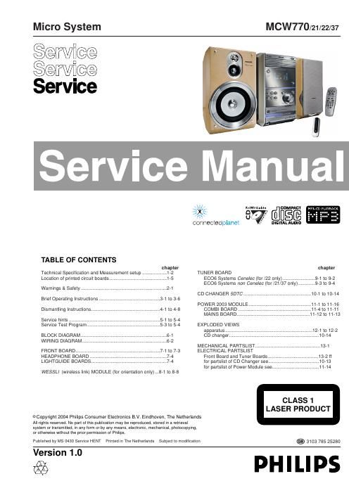
Philips mcw 770 21 22 37 service manual

This is the 77 pages manual for philips mcw 770 21 22 37 service manual.
Read or download the pdf for free. If you want to contribute, please mail your pdfs to info@audioservicemanuals.com.

Page: 1 / 77
left right
philips mcw 770 21 22 37 service manual

Extracted text from philips mcw 770 21 22 37 service manual (Ocr-read)


Page 1

1-2 TECHNICAL SPECIFICATION General: Mains voltage : 230V±10%, 50Hz for /22 127V/240V +10% -15%, 50-60Hz switchable for for /21 120V±10%, 60Hz for /37 Power consumption :²45W (measured at 1/8 P rated ) ²10W in Standby ²0,5W in ECO Standby Input / Output: Auxiliary / CDR in: input sensitivity :²500mV rms , Aux ²1000mVrms , CDR input impedance : 29kW Headphone: output level : max. 2,5V rms at100½ frequency response : 40Hz - 16.000 Hz ±3dB (typ. ±1dB), measured in JAZZ mode distortion :²1% (typ. 0,15%) at 1 kHz and -20dB output level at 120W channel difference :²1dB at 1 kHz channel crosstalk :²-35dB at 1kHz (typ. -60dB) signal/noise ratio :³60dB (A-weighted) Amplifier: Power stage protection : shortcircuit and DC Output power : 2 x 70W rms +0,6dB at 6WD=10% frequency response: 40Hz - 16000Hz ±3dB (typ. ±1dB), measured in JAZZ mode distortion :²1% (typ. 0,15%) at 1 kHz and 1W output power channel difference :²1dB at 1 kHz and 1W output power channel crosstalk :²-35dB at 1kHz (typ. -60dB) signal/noise ratio :³60dB (A-weighted) DC on output :²50mV with no signal on input Digital Sound Control DSC tolerance: ±3dB 60Hz 1kHz 12kHz Jazz (flat) : -1dB 0dB 0dB Rock : +18dB +2,5dB +8dB Pop : +17dB +2dB 0dB Optimal : +9dB +1dB +3,5dB Virtual Environment Control VEC tolerance: ±3dB 60Hz 1kHz 12kHz Jazz (flat) : -1dB 0dB 0dB Cyber : +6,5dB +2dB +5dB Concert : +4,5dB +2dB +3dB Cinema : +7dB +2dB +2dB Hall : +13dB +2dB +1dB Tuner: FM MW (AM) tuning range 87,5 - 108 MHz 531 - 1602 kHz (530 - 1700 kHz for /21/37) IF 10,7 MHz ± 20 kHz 450kHz ± 1 kHz sensitivity Mono: 26dB S/N, m=30% ²5 µV ( 2µV typ.)²4mV/m ( 2mV/m typ.) -3 dB limiting point ²5 µV ( 2µV typ.) frequency grid 50 kHz 9 kHz (100 kHz for /37) (10 kHz for /37) (50/100 kHz* for /21) (9/10 kHz* for /21) * can be selected via software initialization distortion²3% (²1% typ.)²5% ( 3% typ.) RF=1mV Æf=75kHz RF=50mV/m m=80% image rejection ratio³25dB (40dB typ.)³28dB channel separation at 1kHz³22dB (27dB typ.) ----

Page 2

CD module: To be measured on COMBI BOARD connector 1015 . frequency response : 20Hz - 20.000 Hz ±3dB signal/noise ratio :³76dB (A-weighted) distortion :²0,5% at 1 kHz) channel difference :²1dB at 1 kHz channel crosstalk :²-60dB at 1kHz de emphasis : 0 or 15/50µs switched automatically by subcode on the disc laser output power : 500µW wave length : 780 ±20nm Wireless module ãWESSLIÒ: To be measured on COMBI BOARD connector 1022 . frequency response : 20 - 20.000 Hz ±3dB signal/noise ratio :³94dB (A-weighted) distortion :²0,05% at 1 kHz) channel difference :²1dB at 1 kHz channel crosstalk :²-75dB at 1kHz Measurement setup L R LEVEL METERe.g. Sennheiser UPM550 with FF-filter S/N and distortion metere.g. Sound Technology ST1700B DUT CD Use Audio Signal Disc SBC429 4822 397 30184 (replaces test disc 3) Bandpass 250Hz-15kHz e.g. 7122 707 48001 LF Voltmeter e.g. PM2534 DUT S/N and distortion meter e.g. Sound Technology ST1700B Frame aeriale.g. 7122 707 89001 Tuner AM (MW,LW) To avoid atmospheric interference all AM-measurements have to be carried out in a Faraday´s cage. Use a bandpass filter (or at least a high pass filter with 250Hz) to eliminate hum (50Hz, 100Hz). RF Generator e.g. PM5326 Ri=50W Bandpass 250Hz-15kHz e.g. 7122 707 48001 LF Voltmeter e.g. PM2534 DUT RF Generator e.g. PM5326 S/N and distortion meter e.g. Sound Technology ST1700B Use a bandpass filter to eliminate hum (50Hz, 100Hz) and disturbance from the pilottone (19kHz, 38kHz). Ri=50W Tuner FM 1-3 TECHNICAL SPECIFICATION