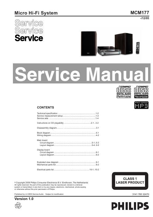
Philips mcm 177 service manual

This is the 20 pages manual for philips mcm 177 service manual.
Read or download the pdf for free. If you want to contribute, please mail your pdfs to info@audioservicemanuals.com.

Page: 1 / 20
left right
philips mcm 177 service manual

Extracted text from philips mcm 177 service manual (Ocr-read)


Page 1

AMPLIFIER Output pow er....................................... .2x10W RMS Signal-to-noise ratio.......................... -‰¥ 60 d BA (IEC) Frequency respons e...................... .125 -“ 16000 Hz Impedance loudspea kers.......................................... .4-„¦ CD PL AYER Frequency rang e.............................. .125 -“ 16000 Hz Signal-to-noise ratio........................................... .65 d BA TUNER FM w averang e.................................. .87.5 -“ 108 MHz Sensitivity at 75 -„¦ -“ FM 26 dB sensitivit y......................................... .20 µV Total ha rmonic disto rtion..................................... -‰¤ 5% SPEAKERS Bass reflex system Dimensions (w x h x d ).160 x 250 x 180 (mm) GENERAL INFORM ATION ACPower................................. 100 -“ 240 V,50/60 Hz Dimensions (w x h x d ).....232 x 85 x 275 (mm) Weight (with spea kers)......................... .appr ox. 5 kg Powerconsumption Acti ve........................................................................\ . .30 W Stand by................................................................... .<5W Eco Power Stand by.......................................... .< 1 W Specifications and external appea rance a re subject to change without notic e. TECHNICAL SPECIFICATION 1 - 2

Page 2

1-3 LF Generator e.g. PM5110 Recorder Use Universal Test Cassette CrO2SBC419 4822 397 30069 LEVEL METERe.g. Sennheiser UPM550 with FF-filter S/N and distortion met e e.g. Sound Technology ST170 L R DUT or Universal Test Cassette FeSBC420 4822 397 30071 LEVEL METERe.g. Sennheiser UPM550 with FF -filter S/N and distortion metere.g. Sound Technology ST1700B L R DUT CD Use Audio Signal Disc (replaces test disc 3) SBC429 4822 397 30184 Bandpass 250Hz-15kHz e.g. 7122 707 48001 LF Voltmeter e.g. PM2534 DUT S/N and distortion meter e.g. Sound Technology ST1700B Frame aeriale.g. 7122 707 89001 Tuner AM (MW,LW) To avoid atmospheric interference all AM-measurements have to be carried out in a Faraday´s cage. Use a bandpass filter (or at least a high pass filter with 250Hz) to e\ liminate hum (50Hz, 100Hz). RF Generator e.g. PM5326 Ri=50 : Bandpass 250Hz-15kHz e.g. 7122 707 48001 LF Voltmeter e.g. PM2534 DUT RF Generator e.g. PM5326 S/N and distortion meter e.g. Sound Technology ST1700B Use a bandpass filter to eliminate hum (50Hz, 100Hz) and disturbance f\ rom the pilottone (19kHz, 38kHz). Ri=50 : Tuner FM MEASUREMENT SETUP