Philips fw d 16 17 service manual

This is the 49 pages manual for philips fw d 16 17 service manual.
Read or download the pdf for free. If you want to contribute, please mail your pdfs to info@audioservicemanuals.com.

Page: 1 / 49
left right
philips fw d 16 17 service manual

Extracted text from philips fw d 16 17 service manual (Ocr-read)


Page 1

Mini System FWD16, FWD17

Serwfiee
Serwgee
Servrce

all versions

ervice Manua

MPZVCD PLAYBACK
- n n.- n.
= u
u u-

VIDEO CD v. D E 0 Wu + R-wnuhh

[LE-SE @fiEE EEE EEE

_IGITALV1DEO mgr-m, Aunln Recordable ' eWritabI -

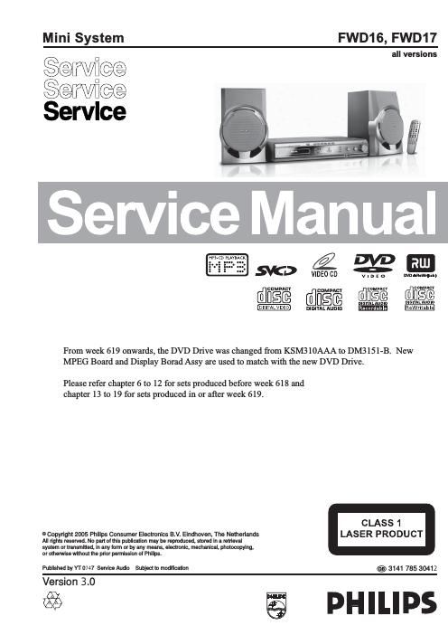
From week 619 onwards, the DVD Drive was changed from KSM310AAA to DM3151-B. New
MPEG Board and Display Borad Assy are used to match with the new DVD Drive.

Please refer chapter 6 to 12 for sets produced before week 618 and
chapter 13 to 19 for sets produced in or after week 619.

CLASS 1

© Copyright 2005 Philips Consumer Electronics B.V. Eindhcven, The Netherlands LAS ER PRODUCT
All rights reserved. No part ol this publication may be reproduced, stored in a retrieval
system or transmitted, in any lorm or by any means, electronic, mechanical, photocopying,
or otherwise without the prior permission of Philips.

Published by YT 0747 Service Audio Subject to modification 3141 785 30412

Version 3.0 pH I Ll ps

2%

Page 2

TABLE OF CONTENTS

Handling chip components
Service tools .....................
Leadfree and safety information ..
Technical specification ...........
Service measurement setup..
Connections and controls ......

Disassembly diagram
Service Test Program .....

For sets produced before week 618

(GW1006180xxxxx)
Block diagram... ..... 6-1
Wiring diagram . ..... 6-2
Display / Tuner board
circuit diagram ..... 7-1
layout diagram ..... 7-2
Main and Power board
circuit diagram ..................................................... 8-1
layout diagram ............................................. 8-2...8-3
Cassette board
circuit diagram. .. ..... 9-1
layout diagram ..... 9-2
DVD / MPEG board
circuit diagram .................. 10-1
layout diagram ..... ...10-2...10-3

Exploded view diagram ..
Mechanical partslist ........

Electrical partslist .................................................. 12-1

For sets produced in or after week 618
(GW2006190xxxxx up)

13-1
132

Block diagram .....
Wiring diagram ..

Display / Tuner board
circuit diagram ......
layout diagram ......

14-1
14-2

Main and Power board
circuit diagram ................................................... 15-1
layout diagram ......................................... 15-2...15-3

Cassette board
circuit diagram. .....
layout diagram ......

16-1
162

DVD / MPEG board
circuit diagram .....
layout diagram .....

...17-4
17-5

184
18-2

Exploded view diagram
Mechanical partslist .........

Electrical partslist ........................................ 19-1...19-3

Revision ................................................................. 20<1