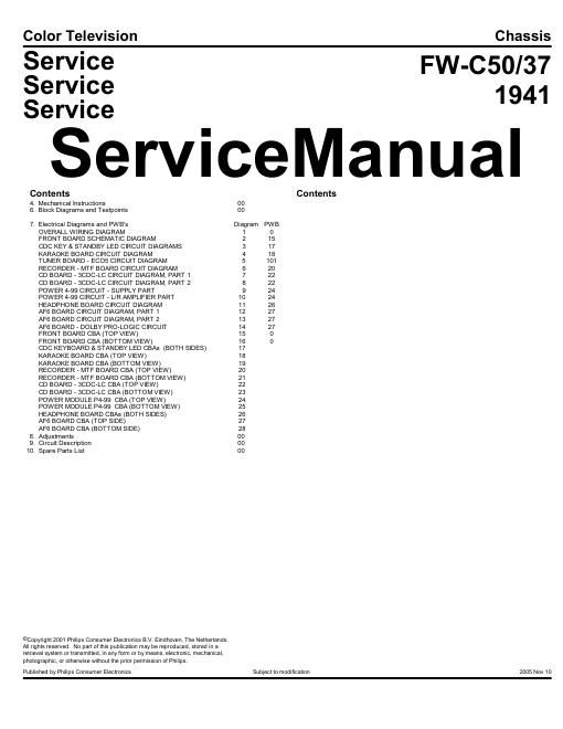
Philips fw c 50 service manual

This is the 132 pages manual for philips fw c 50 service manual.
Read or download the pdf for free. If you want to contribute, please mail your pdfs to info@audioservicemanuals.com.

Page: 1 / 132
left right
philips fw c 50 service manual

Extracted text from philips fw c 50 service manual (Ocr-read)


Page 1

GENERAL SAFETY NOTES IMPORTANT SAFETY NOTICE Proper service and repair is important to the safe, reliable operation of all Philips Consumer Electronics Company** equipment. The service procedures recommended by Philips and described in this service manual are effective methods of performing service operations. Some of these service operations require the use of tools specially designed for the purpose. The special tools should be used when and as recommended. It is important to note that this manual contains various CAUTIONS and NOTICES which should be carefully read in order to minimize the risk of personal injury to service personnel. The possibility exists that improper service methods may damage the equipment. It also is important to understand that these CAUTIONS and NOTICES ARE NOT EXHAUSTIVE. Philips could not possibly know, evaluate and advise the service trade of all conceivable ways in which service might be done or of the possible hazardous consequences of each way. Consequently, Philips has not undertaken any such broad evaluation. Accordingly, a servicer who uses a service procedure or tool which is not recommended by Philips must first satisfy himself thoroughly that neither his safety nor the safe operation of the equipment will be jeopardized by the service method selected. ** Hereafter throughout this manual, Philips Consumer Electronics Company will be referred to as Philips. WARNING Critical components having special safety characteristics are identified with a or "S" by the Ref. No. in the parts list and enclosed within a broken line* (where several critical components are grouped in one area) along with the safety symbol on the schematics or exploded views. Use of substitute replacement parts which do not have the same specified safety characteristics may create shock, fire, or other hazards. Under no circumstances should the original design be modified or altered without written permission from Philips. Philips assumes no liability, express or implied, arising out of any unauthorized modification of design. Servicer assumes all liability. -Broken Line ____ _ ____ _ ____ _ ____ SAFETY CHECKS After the original service problem has been corrected, a complete safety check should be made. Be sure to check over the entire set, not just the areas where you have worked. Some previous servicer may have left an unsafe condition, which could be unknowingly passed on to Your customer. Be sure to check all of the following: FIRE AND SHOCK HAZ ARD IMPLOSION X-RADIAT ION LEAKAGE CURRENT COLD CHECK LEAKAGE CURRENT HOT CHECK

Page 2

PICT URE T UBE REPLACEM ENT PARTS REPLACEMENT FIRE AND SHOCK HAZARD 1. Be sure all components are positioned in such a way as to avoid the possibility of adjacent component shorts. This is especially important on those chassis which are transported to and from the service shop. 2. Never release a repaired unit unless all protective devices such as insulators, barriers, covers, strain reliefs, and other hardware have been installed in accordance with the original design. 3. Soldering and wiring must be inspected to locate possible cold solder joints, solder splashes, sharp solder points, frayed leads, pinched leads, or damaged insulation (including the ac cord). Be certain to remove loose solder balls and all other loose foreign particles. 4. Check across-the-line components and other components for physical evidence of damage or deterioration and replace if necessary. Follow original layout, lead length, and dress. 5. No lead or component should touch a receiving tube or a resistor rated at 1 watt or more. Lead tension around protruding metal surfaces or edges must be avoided. 6. Critical components having special safety characteristics are identified with an 'S' by the Ref. No. in the parts list and enclosed within a broken line* (where several critical components are grouped in one area) along with the safety symbol on the schematic diagrams and /or exploded views. 7. When servicing any unit, always use a separate isolation transformer for the chassis. Failure to use a separate isolation transformer may expose you to possible shock hazard, and may cause damage to servicing instruments. 8. Many electronic products use a polarized ac line cord (one wide pin on the plug). Defeating this safety feature may create a potential hazard to the servicer and the user. Extension cords which do not incorporate the polarizing feature should never be used. 9. After reassembly of the unit, always perform an ac leakage test or resistance test from the line cord to all exposed metal parts of the cabinet. Also, check all metal control shafts (with knobs removed), antenna terminals, handles, screws, etc., to be sure the unit may be safely operated without danger of electrical shock. * Broken line ____ _ ____ _ ____ _ ____ IMPLOSION 1. All picture tubes used in current model receivers are equipped with an integral implosion system. Care should always be used, and safety glasses worn, whenever handling any picture tube. Avoid scratching or otherwise damaging the picture tube during installation. 2. Use only replacement tubes specified by the manufacturer.