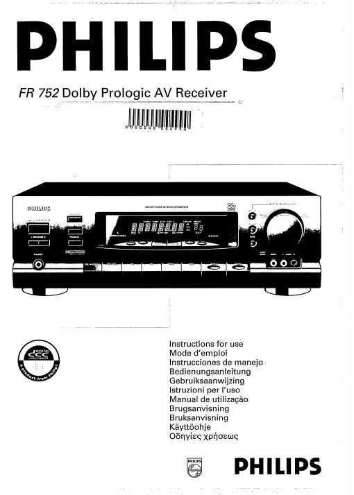
Philips fr 752 owners manual

This is the 14 pages manual for philips fr 752 owners manual.
Read or download the pdf for free. If you want to contribute, please mail your pdfs to info@audioservicemanuals.com.

Page: 1 / 14
left right
philips fr 752 owners manual

Extracted text from philips fr 752 owners manual (Ocr-read)


Page 2

INTRODUCTION INSTALLATION

Thank you for selecting the Philips FR 752 Stereo Receiver.
A part of the state-of-the-art Philips 700 series, the FR 752
receiver is engineered to fulfil the task of generating powerful

WARNING
Do not connect the set to the mains until all other

sound with the highest achieVable definition, minimum noise connections have been made and the mains voltage
and distortion. The FR 752 is supported by features such as: (indicated on the type plate on the back cover) has
been checked.
- A full-function remote control which can handle your entire When positioning the unit, bear in mind that every receiver
PHILIPS 700 series HiFi system, as well as a W set and a produces heat which must be able to dissipate freely. For
Vlde° cassette recorder. this reason do not cover any vents and make sure that

- RC-5 BUS, offering increased ease of operation by extensive there is sufficient ventilation around the unit.
communication between the various components of your
system.

- High-precision, drift free quartz-locked digital tuning on two MAINS SUPPLY
wavebands.

- 30 frequencies can be stored in the memory.

- Check that the mains voltage as shown on the type plate
corresponds to your local mains supply. If it does not. consult
your dealer or a Philips Authorized Service Centre.

Please read this manual carefully before you attempt to 0 Insert the plug of the mains lead into the wall socket.
connect or operate the amplifier. - The power supply is now connected.
- To disconnect the set from the mains completely, remove
This manual is divided into seven sections: the mains plug from the W3" socket.
- Installation: explains how to set up your system
- page 3, 4, 5.

- Functional overview: explains how to use the major
controls - page 6. 7, 8.

- Amplifier: gives more detailed information on operation of
the amplifier section of your receiver - page 9.10.

- Tuner: gives more detailed information on operation of the
tuner section of your receiver - page 11, 12.

- Other possibilities: explains the sleep-timer function and
the VCR dubbing mode - page 12.

- Additional information: includes maintenance information
and technical data - page 13.

- Troubleshooting : gives information on possible causes of
problems and how to solve them - page 14.

The type plate is located at the rear of the set.

This product complies with the radio interference requirements
of the European Community

Important notes for users in the UK:

Mains plug

This apparatus is fitted with an approved 13 Amp plug.

To change a fuse in this type of plug proceed as follows:

1 Remove fuse cover and fuse.

2 Fix new fuse which should be a 351362 5 AMP. A.S.T.A. or BSI approved type.
3 Flefit the fuse cover.

if the fitted plug is not suitable for your socket outlets, it should be cut off and an appropriate plug fitted in its place.

if the mains plug contains a fuse, this should have a value of 5 A. lf a plug without a fuse is used, the fuse at the distribution
board should not be greater than 5 A.

Note: The severed plug must be disposed to avoid a possible shock hazard should it be inserted into a 13 A socket elsewhere.

How to connect a plug

The wires in the mains lead are coloured in accordance with the following code: blue = neutral (N). brown = live (L).

As these colours may not correspond with the colour markings identifying the terminals in your plug, proceed as follows:

1 Connect the blue wire to the terminal marked N or coloured blue or black.

2 Connect the brown wire to the terminal marked L or coloured brown or red.

3 Do not connect either wire to the earth terminal in the plug, marked E or e or coloured green or green-and-yellow.

Before replacing the plug cover, make certain that the cord grip is clamped over the sheath of the lead - not simply over the two
Wires.

if in doubt, consult a qualified electrician.

English