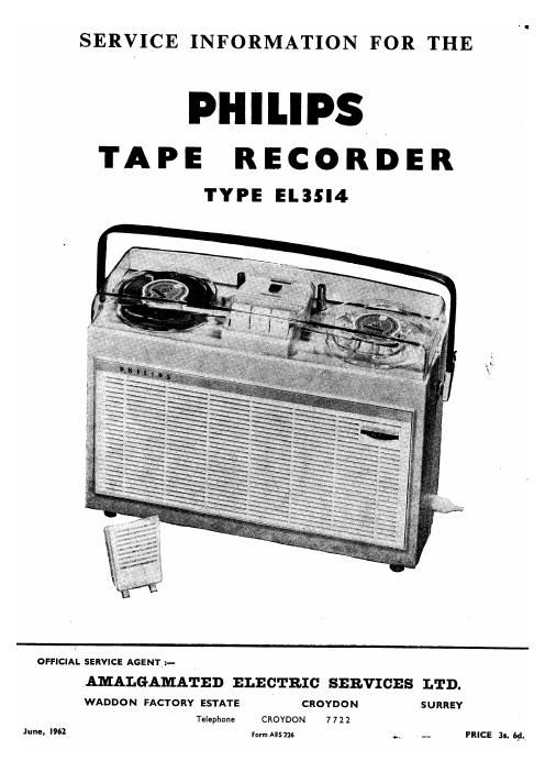
Philips el 3514 service manual

This is the 16 pages manual for philips el 3514 service manual.
Read or download the pdf for free. If you want to contribute, please mail your pdfs to info@audioservicemanuals.com.

Page: 1 / 16
left right
philips el 3514 service manual

Extracted text from philips el 3514 service manual (Ocr-read)


Page 2

Vintage Service Data CD-Ftom

A. - GENERAL DESCRIPTION

B. - OPERATION

C. - SPECIFICATION

D. - REMOVING THE CABINET

E. - MECHANICAL DESCRIPTION

F. - MECHANICAL CHECKS AND ADJUSTMENTS
G. - REPLACEMENT 0F BOWDEN CABLES

H. - MODIFICATION FOR 60C/S SUPPLY

I. -- ELECTRICAL DESCRIPTION

J. - ELECTRICAL TESTS AND ADJUSTMENTS
K. - OVERALL FREQUENCY RESPONSE

L. - CLEANING AND LUBRICATION

M. - SPARES LIST

A.-GENERAL DESCRIPTION

The EL.3514/ 15 is a single speed four track tape recorder,
mains operated, providing up to four hours playing time from
a single tape.

Recordings may be made from microphone, gramophone
and radio (diode).

An internal speaker of 6; diameter is fitted, also sockets
for extension loudspeaker and external amplifier.
B.-OPERATION

Refer to booklet supplied with each machine.
C.-SPECIF1CATION
Tape Speed 3i'/sec.

Max. Reel Diameters 4" with lid fitted, 5' Without lid.
Forward Wind/ 600 ft. of tape in under 130 secs.
Rewind Speed
Frequency Response 80 c/s to 10 Kc/s.
Mains Voltage 110-127V and 220-240V A.C. 50 c/s.

Ranges (adaptable for 60 c/s).
Consumption Approximately 25 watts.
Output 1.5 watts.
Cabinet demensions Width Height Depth
l4 9% 41
Weight 10:} lbs.
Loudspeaker 61 diameter.

Transistor and valves AC107, ECC83, EL95 and DM71.
Signal to Noise Ratio Better than 40 db.
Wow and Flutter Less than 1.0%.

Microphone Type EL3756/00 omni-directional moving
coil, 5009 impedance.

Inputs
Microphone 0.2mV, 3K (1. SKT 1.
Gramophone 130mV, 2.2m Q. SKT 3 Connected in
Gramophone ,, n SKT 4 parallel.
Radio (diode) 3.0mV, 50K 9. SKT 2 (pins 1 and 2).
Radio (diode),

via Lead

EL3768/01. 100mV, 1.5m Q. SKT 2. (see Fig. 19)

Outputs
Extension 1.5 watts, 3-7 0. SKT 5.
Loudspeaker
External 1 volt, 30K 9. SKT 2 (pins 3 and 5).
Amplifier

Controls (see Fig. l).

Playback button 87, Rewind button 88, Forward wind
button 89, Record button 146 (used in conjunction with play-
back button).

Track selector button 183, when depressed, locks down for
operation on tracks 1 or 4. To use tracks 2 or 3, release button
by pressing it again.

Volume Control and mains switch 351.

D.-REMOVAL OF CABINET

This is in two halves and may be separated as follows.
Remove the base screws, side circlips 367 and all four screws 373
in top of the cabinet. Front half of cabinet is removed first,
due to tongue and groove in respective halves of cabinet.

E.-DESCR[PTION 0F MECHANISM (see Fig. 20)

1. Playback

When the playback button 87 is operated, the push bar 84 moves
the brake slide 83 to the right, releasing brakes 99, 100 and the
R.H. friction pad 12013.

Tape tension is maintained by the L.H. turntable friction pad
120A. Push bar 34 also moves the carriage bracket 57 forward,
bringing both pressure pads into contact with the head faces
and the pressure roller into contact with the capstan l7. Carriage
bracket 57, in turn, moves the slipping clutch assembly 42 into
contactsévith the flywheel and the rubber rim on the R.H. turn-
table .

The flywheel [capstan is driven by belt 18 from pulley 203 on the
motor 151.

In addition, push bar 84 operates S 4 and S 5, bringing external
amplifier and Ioudspwker sockets into circuit.

2. Record

The record button 146 is held down then locked in position by
the operation of the playback button 87. The tongue on the
locking bracket 65 engaging a slot in the record button 146,
which in turn operates S 1 and S 2 via Bowden cable 344.

3. Forward Wind

When forward wind button 89 is operated, both brakes and
friction pad are released as described in El. Push bar 84 moves
the winding roller assembly 49 into contact with the flywheel l7
and the rubber rim on the R.H. turntable. Tape tension is
again maintained by friction pad 120A.

4. Rewind

When button 88 is operated, brakes and friction pad 120A are
released, and winding roller 112 is engaged with the flywheel.
The pulley on the winding roller transmits drive via belt 182 to
L.H. turntable 179. Tape tension is maintained by friction
pad 12013.

F. MECHANICAL CHECKS AND ADJUSTMENTS (see
Fig. 20).
1. Motor and Fan Pulley
(1) Motor 151
The Motor may be removed for service by releasing the
three screws in the top plate and detaching the drive
bet 18.
(ii) Motor bearings
When replacing either of the motor bearings, centering
feelers should be used to ensure adequate clearance
between rotor and stator. End play in shaft should be
adjusted to approximately 0.5 mm. by screw and locknut.
(iii) Fan pulley
To remove pulley loosen grub screw and pull off.
Slide replacement on to motor shaft until the end of
shaft extends 0.5 mm. beyond pulley. Tighten grub
screw.
2. Turntables and Tape Guides
(1) Turntables 179, 180.
The height of each turntable should be adjusted so
that the top edge of the turntable is 14 mm. above the
top plate. Adjustments are made by rotating thenylon
bearing screws 181.

Page One

www. vin tage-radio. com