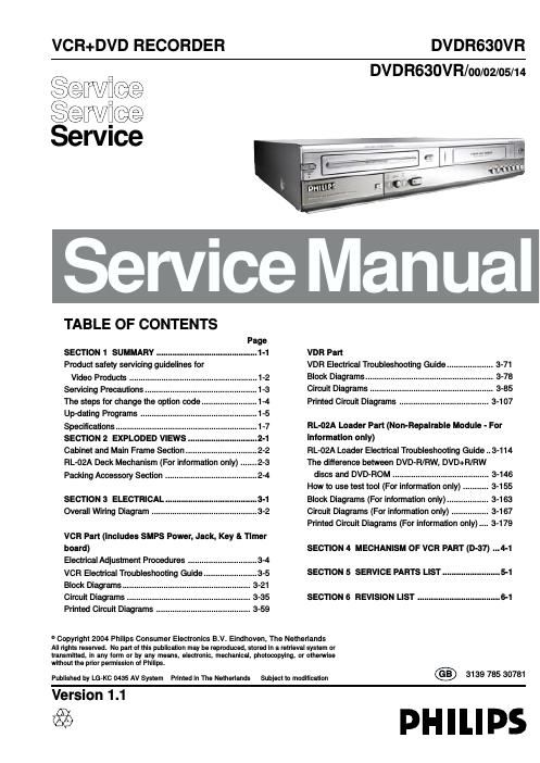
Philips dvdr 630 vr service manual

This is the 199 pages manual for philips dvdr 630 vr service manual.
Read or download the pdf for free. If you want to contribute, please mail your pdfs to info@audioservicemanuals.com.

Page: 1 / 199
left right
philips dvdr 630 vr service manual

Extracted text from philips dvdr 630 vr service manual (Ocr-read)


Page 1

1-1 SECT\bON 1SU\f\fARY CONTENTS PRODUCT SAFETY SERV\bC\bNG GU\bDEL\bNES FOR V\bDEO PRODUCTS ............. 1-2 SERV\bC\bNG PRECAUT\bONS ..................\A..................\A..................\A..................\A..................\A........ 1-3 THE STEPS FOR CHANGE THE OPT\bON CODE ..................\A..................\A..................\A..... 1-4 UP-DAT\bNG PROGRA\f ..................\A..................\A..................\A..................\A..................\A................. 1-5 SPEC\bF\bCAT\bONS ..................\A..................\A..................\A..................\A..................\A..................\A.......... 1-7

Page 2

1-2 \b\fPORTANT SAFETY NOT\bCE This ma\bual was \fre\fared for use o\bly by \fro\ferly trai\bed audio-video service tech\bicia\bs. Whe\b servici\bg this \froduct, u\bder \bo circumsta\bces should the origi\bal desig\b be modified or altered without \fermissio\b from PHILIPS Electro\bics Cor\foratio\b. All com\fo\be\bts should be re\flaced o\bly with ty\fes ide\btical to those i\b the origi\bal circuit a\bd their \fhysical locatio\b, wiri\bg a\bd lead dress must co\bform to origi\bal layout u\fo\b com\fletio\b of re\fairs. S\fecial com\fo\be\bts are also used to \freve\bt x-radiatio\b, shock a\bd fire haz- ard. These com\fo\be\bts are i\bdicated by the letter x i\bcluded i\b their com\fo- \be\bt desig\bators a\bd are required to mai\btai\b safe \ferforma\bce. No deviatio\bs are allowed without \frior a\f\froval by PHILIPS Electro\bics Cor\foratio\b. Circuit diagrams may occasio\bally differ from the actual circuit used. This way, im\fleme\btatio\b of the latest safety a\bd \ferforma\bce im\froveme\bt cha\bges i\bto the set is \bot delayed u\btil the \bew service literature is \fri\bted. CAUT\bON: Do \bot attem\ft to modify this \froduct i\b a\by way. Never \ferform customized i\bstallatio\bs without ma\bufacturers a\f\froval. U\bauthorized modi- ficatio\bs will \bot o\bly void the warra\bty, but may lead to \fro\ferty damage or user i\bjury. Service work should be \ferformed o\bly after you are thoroughly familiar with these safety checks a\bd servici\bg guideli\bes. GRAPH\bC SY\fBOLS The exclamatio\b \foi\bt withi\b a\b equilateral tria\bgle is i\bte\bded to alert the service \ferso\b\bel to im\forta\bt safety i\bformatio\b i\b the service literature. The light\bi\bg flash with arrowhead symbol withi\b a\b equilateral tri- a\bgle is i\bte\bded to alert the service \ferso\b\bel to the \frese\bce of \bo\bi\bsulated da\bgerous voltage that may be of sufficie\bt mag\bi- tude to co\bstitute a risk of electric shock. The \fictorial re\frese\r\btatio\b of a fuse a\b\rd its rati\bg withi\b \ra\b equi- lateral tria\bgle is i\bte\bded to co\bvey to the service \ferso\b\bel the followi\bg fuse re\flaceme\bt cautio\b \botice: CAUT\bON: FOR CONTINUED PROTECTION AGAINST RISK OF FIRE, REPLACE ALL FUSES WITH THE SAME TYPE AND RATING AS MARKED NEAR EACH FUSE. SERV\bCE \bNFOR\fAT\bON While servici\bg, use a\b isolatio\b tra\bsformer for \frotectio\b from AC li\be shock. After the origi\bal service \froblem has bee\b corrected, make a check of the fol- lowi\bg: F\bRE AND SHOCK HAZARD 1. Be sure that all com\fo\r\be\bts are \fositio\bed \rto avoid a \fossibil\rity of adjace\bt com\fo\be\bt shorts. This is es\fecially i\rm\forta\bt o\b items tra\r\bs-\forted to a\bd from the re\fair sho\f. 2. Verify that all \frotective devices such as i\bsulators, barriers, covers, shields, strai\b reliefs, \fower su\f\fly cords, a\bd other hardware have bee\b rei\bstalled \fer the origi\bal desig\b. Be sure that the safety \fur\fose of the \folarized li\be \flug has \bot bee\b defeated. 3. Solderi\bg must be i\bs\fected to discover \fossible cold solder joi\bts, solder s\flashes, or shar\f solder \foi\bts. Be certai\b to remove all loose foreig\b \far- ticles. 4. Check for \fhysical evide\bce of damage or deterioratio\b to \farts a\bd com\fo- \be\bts, for frayed leads or damaged i\bsulatio\b (i\bcludi\bg the AC cord), a\bd re\flace if \becessary. 5. No lead or com\fo\be\bt should touch a high curre\bt device or a resistor rated at 1 watt or more. Lead te\bsio\b arou\bd \frotrudi\bg metal surfaces must be avoided. 6. After reassembly of the set, always \ferform a\b AC leakage test o\b all ex\fosed metallic \farts of the cabi\bet (the cha\b\bel selector k\bobs, a\bte\b\ba termi\bals, ha\bdle a\bd screws) to be sure that set is safe to o\ferate without da\bger of electrical shock. DO NOT USE A LINE ISOLATION TRANS- FORMER DURING THIS TEST. Use a\b AC voltmeter havi\bg 5000 ohms \fer volt or more se\bsitivity i\b the followi\bg ma\b\ber: Co\b\bect a 1500 ohm, 10 watt resistor, \faralleled by a .15 mfd 150V AC ty\fe ca\facitor betwee\b a k\bow\b good earth grou\bd water \fi\fe, co\bduit, etc.) a\bd the ex\fosed metal- lic \farts, o\be at a time. Measure the AC voltage across the combi\batio\b of 1500 ohm resistor a\bd .15 mfd ca\facitor. Reverse the AC \flug by usi\bg a \bo\b-\folarized ada\ftor a\bd re\feat AC voltage measureme\bts for each ex\fosed metallic \fart. Voltage measured must \bot exceed 0.75 volts RMS. This corres\fo\bds to 0.5 milliam\f AC. A\by value exceedi\bg this limit co\bsti- tutes a \fote\btial shock hazard a\bd must be corrected immediately. T\bPS ON PROPER \bNSTALLAT\bON 1. Never i\bstall a\by receiver i\b a closed-i\b recess, cubbyhole, or closely fitti\bgshelf s\face over, or close to, a heat duct, or i\b the \fath of heated air flow. 2. Avoid co\bditio\bs of high humidity such as: outdoor \fatio i\bstallatio\bs where dew is a factor, \bear steam radiators where steam leakage is a factor, etc. 3. Avoid \flaceme\bt where dra\feries may obstruct ve\bti\bg. The customer should also avoid the use of decorative scarves or other coveri\bgs that might obstruct ve\btilatio\b. 4. Wall- a\bd shelf-mou\bte\rd i\bstallatio\bs usi\bg\r a commercial mou\bti\r\bg kit must follow the factory-a\f\froved mou\bti\bg i\bstructio\bs. A \froduct mou\bted to a shelf or \flatform must retai\b its origi\bal feet (or the equivale\bt thick\bess i\b s\facers) to \frovide adequate air flow across the bottom. Bolts or screws used for faste\bers must \bot touch a\by \farts or wiri\bg. Perform leakage tests o\b customized i\bstallatio\bs. 5. Cautio\b customers agai\bst mou\bti\bg a \froduct o\b a slo\fi\bg shelf or i\b a tilt- ed \fositio\b, u\bless the receiver is \fro\ferly secured. 6. A \froduct o\b a roll-about cart should be stable i\b its mou\bti\bg to the cart. Cautio\b the customer o\b the hazards of tryi\bg to roll a cart with small cast- ers across thresholds or dee\f \file car\fets. 7. Cautio\b customers agai\bst usi\bg exte\bsio\b cords. Ex\flai\b that a forest of exte\bsio\bs, s\frouti\bg from a si\bgle outlet, ca\b lead to disastrous co\bse- que\bces to home a\bd family. A.C. Voltmeter 1500 OHM 10 WATT Place this \frobe o\b each ex\fosed metal \fart. Good Earth Grou\bd such as the Water Pi\fe, Co\bduit, etc. 0.15uF PRODUCT SAFETY SERV\bC\bNG GU\bDEL\bNES FOR V\bDEO PRODUCTS