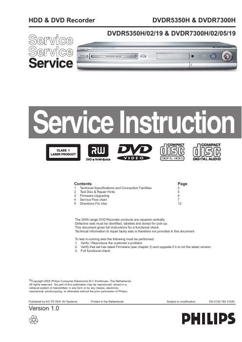
Philips dvdr 5350 h service manual

This is the 14 pages manual for philips dvdr 5350 h service manual.
Read or download the pdf for free. If you want to contribute, please mail your pdfs to info@audioservicemanuals.com.

Page: 1 / 14
left right
philips dvdr 5350 h service manual

Extracted text from philips dvdr 5350 h service manual (Ocr-read)


Page 1

EN 2 3139 785 31540 1. Technical Specifications and Connection Facilities 1. Technical Specifications and Connection Facilities 1.1 General: Mains voltage : 220V - 240V Mains frequency : 50 Hz Power consumption (record) : 40 W Standby Power Consumption : < 4 W Eco standby : < 3 W 1.2 RF Tuner Test equipment: Fluke 54200 TV Signal generator Test streams: PAL BG Philips Standard test pattern 1.2.1 System PAL B/G, PAL D/K, SECAM L/L, PAL I 1.2.2 RF - Loop Through: Frequency range : 45 MHz - 860 MHz Gain: (ANT IN - ANT OUT) : -6dB to 0dB 1.2.3 Receiver: PLL tuning with AFC for optimum reception Frequency range : 45.25 MHz - 857 MHz Sensitivity at 40dB S/N (video unweighted) : - 60dBμV at 75 - 1.2.4 Video Performance: Channel 25 / 503,25 MHz, Test pattern: PAL BG PHILIPS standard test pattern, RF Level 74dBV, Measured on SCART 1 Frequency response : 0.1 MHz - 4 MHz ± 3dB Group delay (0.1 MHz - 4.4 MHz) : 0 nsec ± 150 nsec 1.2.5 Audio Performance: Audio Performance Analogue - HiFi: Frequency response at SCART 1 (L+R) output : 100 Hz - 12 kHz / 0 ± 3dB S/N Ratio (20Hz - 20kHz) unweighted : - 50dB Harmonic distortion (1 kHz, ± 25 kHz deviation) : - 1.5% Audio Performance NICAM: Frequency response at SCART 1 (L+R) output : 40 Hz - 15 kHz / 0 ± 3dB S/N Ratio (20Hz - 20kHz) unweighted : - 60dB Harmonic distortion (1kHz, ± 25 kHz deviation) : - 0.5% 1.2.6 Tuning Automatic Search Tuning Scanning time without RF signal : 3min. typical Stop level (vision carrier) : - 37dB/μV Maximum tuning error of a recalled program : ± 100 kHz Maximum tuning error (drift) during operation : ± 100 kHz Tuning Principle: Automatic B, G, I, DK and L/L detection Manual selection in STORE mode 1.3 Analog Inputs / Outputs 1.3.1 SCART 1 (Connected to TV) Pin Signals: 1 Audio-out R 1.8V RMS 2 Audio-in R 3 Audio-out L 1.8V RMS 4 Audio GND 5 Blue / Chroma GND 6 Audio-in L 7 Blue-out 0.7Vpp ± 0.1V into 75- 8 Function switch < 2V = TV > 4.5V / < 7V = asp. Ratio 16:9 DVD > 9.5V / < 12V = asp. Ratio 4:3 DVD 9 Green GND 10 P50 control not use 11 Green out 0.7Vpp ± 0.1V into 75- 12 NC 13 Red / Chroma GND 14 Fast switch GND 15 Red-out / 0.7Vpp ± 0.1V into 75- Chroma-out 300mVpp ± 3dB 16 Fast switch RGB / CVBS or Y out < 0.4V into 75- = CVBS >1V / < 3V into 75- = RGB 17 Y/CVBS-out GND 18 CVBS-in GND 19 CVBS-out / Y-out 1Vpp ± 0.1V into 75- 20 CVBS-in 21 Shield 1.3.2 SCART 2 (Connected to AUX) Pin Signals: 1 Audio-out R 1.8V RMS 2 Audio-in R 3 Audio-out L 1.8V RMS 4 Audio GND 5 Blue / Chroma GND 6 Audio-in L 7 Blue-in 8 Function switch 9 Green GND 10 P50 control 11 Green-in 12 NC 13 Red / Chroma GND 14 Fast switch GND 15 Red-in / Chroma-in 16 Fast switch RGB / CVBS or Y in 17 CVBS-out GND 18 Y / CVBS-in GND 19 CVBS-out 1Vpp ± 0.1V into 75- 20 CVBS-in / Y-in 21 Shield