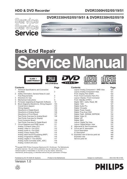
Philips dvdr 3330 h service manual

This is the 161 pages manual for philips dvdr 3330 h service manual.
Read or download the pdf for free. If you want to contribute, please mail your pdfs to info@audioservicemanuals.com.

Page: 1 / 161
left right
philips dvdr 3330 h service manual

Extracted text from philips dvdr 3330 h service manual (Ocr-read)


Page 1

EN 2 3139 785 31150 1. Technical Specifi cations and Connection Facilities 1. Technical Specifi cations and Connection Facilities 1.1 PCB Locations 1.2 Diversity Matrix DVDR3300H DVDR3330H DVDR5330H HDD capacity 80GB 160GB 250GB 1.3 Read / Write Speed Type of Disc (Function) Disc Rotation Speed Read Speed CD 7X CAV Read Speed DVD 4X CAV Write Speed DVD+R/+RW 2.4X ZCAV Write Speed DVD-R/-RW 2X 1.4 General: Mains voltage : 220V - 240V Mains frequency : 50 Hz Power consumption (record) : 40 W Standby Power Consumption : < 6 W 1.5 RF Tuner Test equipment: Fluke 54200 TV Signal generator Test streams: Philips Standard test pattern 1.5.1 System PAL B/G, PAL D/K, SECAM L/L, PAL I 1.5.2 RF - Loop Through: Frequency range : 45 MHz - 860 MHz Gain: (ANT IN - ANT OUT) : -5dB to 0dB1.5.3 Receiver: PLL tuning with AFC for optimum reception Frequency range : 45.25 MHz - 857 MHz Sensitivity at 40dB S/N (video unweighted) : - 60dBμV at 75 Ω 1.5.4 Video Performance: Channel 25 / 503,25 MHz, Test pattern: PAL BG PHILIPS standard test pattern, RF Level 74dBV, Measured on SCART 1 Frequency response : 0.1 MHz - 4 MHz ± 3dB Group delay (0.1 MHz - 4.4 MHz) : 0 nsec ± 150 nsec 1.5.5 Audio Performance: Audio Performance Analogue - HiFi: Frequency response at SCART 1 (L+R) output : 100 Hz - 12 kHz / 0 ± 3dB S/N Ratio (20Hz - 20kHz) unweighted : - 50dB Harmonic distortion (1kHz, ± 25 kHz deviation) : - 0.5% Audio Performance NICAM: Frequency response at SCART 1 (L+R) output : 40 Hz - 15 kHz / 0 ± 3dB S/N Ratio (20Hz - 20kHz) unweighted : - 60dB Harmonic distortion (1kHz, ± 25 kHz deviation) : - 0.5% Analog Board Basic Engine Front Boards (Behind the Front Plate) HDD Digital Board PSU Board

Page 2

EN 3 3139 785 311501. Technical Specifi cations and Connection Facilities 1.5.6 Tuning Automatic Search Tuning Scanning time without RF signal : 3min. typical Stop level (vision carrier) : - 37dB/μV Maximum tuning error of a recalled program : ± 100 kHz Maximum tuning error (drift) during operation : ± 100 kHz Tuning Principle: Automatic B, G, I, DK and L/L detection Manual selection in STORE mode 1.6 Analog Inputs / Outputs 1.6.1 SCART 1 (Connected to TV) Pin Signals: 1 Audio-out R 1.8V RMS 2 Audio-in R 3 Audio-out L 1.8V RMS 4 Audio GND 5 Blue / Chroma GND 6 Audio-in L 7 Blue-out / 0.7Vpp ± 0.1V into 75Ω Chroma-in 8 Function switch < 2V = TV > 4.5V / < 7V = asp. Ratio 16:9 DVD > 9.5V / < 12V = asp. Ratio 4:3 DVD 9 Green GND 10 P50 control not use 11 Green out 0.7Vpp ± 0.1V into 75Ω 12 NC 13 Red / Chroma GND 14 Fast switch GND 15 Red-out / 0.7Vpp ± 0.1V into 75Ω Chroma-out 300mVpp ± 3dB 16 Fast switch RGB / CVBS or Y < 0.4V into 75Ω = CVBS >1V / < 3V into 75Ω = RGB 17 Y/CVBS-out GND 18 CVBS-in GND 19 CVBS-out / Y-out 1Vpp ± 0.1V into 75Ω 20 CVBS-in 21 Shield 1.6.2 SCART 2 (Connected to AUX) Pin Signals: 1 Audio-out R 1.8V RMS 2 Audio-in R 3 Audio-out L 1.8V RMS 4 Audio GND 5 Blue / Chroma GND 6 Audio-in L 7 Blue-in / Chroma-out 300mVpp ± 3dB 8 Function switch 9 Green GND 10 P50 control 11 Green-in 12 NC 13 Red / Chroma GND 14 Fast switch GND 15 Red-in / Chroma-in 16 Fast switch RGB / CVBS or Y 17 CVBS-out GND 18 Y / CVBS-in GND 19 CVBS-out 1Vpp ± 0.1V into 75Ω 20 CVBS-in / Y-in 21 Shield1.6.3 Audio/Video Front Input Connectors Audio - Cinch Input voltage : 2Vrms Input impedance : > 10kΩ Video - Cinch Input voltage : 1Vpp ± 3dB Input impedance : 75Ω Video - YC (Hosiden) According to IEC 933-5 Superimposed DC-level on pin 4 (load > 100kΩ) < 2.4V is detected as 4:3 aspect ratio > 3.5V is detected as 16:9 aspect ratio Input voltage Y : 1Vpp ± 3dB Input impedance Y : 75Ω Input voltage C : 300mVpp ± 3dB Input impedance C : 75Ω 1.6.4 Audio/Video Output rear Connectors Audio - Cinch Output voltage : 2Vrms max. Output impedance : > 10kΩ Video - Cinch Output voltage : 1Vpp ± 3dB Output impedance : 75Ω Video - YC (Hosiden) According to IEC 933-5 Superimposed DC-level on pin 4 (load > 100kΩ) < 2.4V is detected as 4:3 aspect ratio > 3.5V is detected as 16:9 aspect ratio Output voltage Y : 1Vpp ± 3dB Input impedance : 75Ω Output voltage C : 300mVpp ± 3dB Input impedance : 75Ω 1.7 Digital Inputs / Outputs 1.7.1 Digital Output Digital Audio - Coaxial / Optical LCM : according IEC 60958 MPEG 1, MPEG 2, AC3 : according IEC 61937 DTS : according IEC 61937 + addendum 1.7.2 Digital Video Input (IEEE 1394) Implementation Standard according: IEEE Std 1394-1995 IEC61883 - Part1 IEC61883 - Part 2 SD-DVCR (02-01-1997) Specifi cation of consumer use digital VCRs using 6.3mm magnetic tape - dec.1994 Mechanical connection according to Annex of IEC 61883-1 1.8 Video Performance All outputs loaded with 75Ω SNR measurements over full bandwidth without weighting. 1.8.1 SCART (RGB) SNR : - 55dB on all output Bandwidth : 4.8MHz -3dB