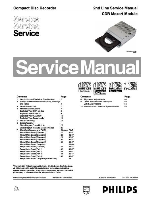
Philips cdr mozart service manual

This is the 62 pages manual for philips cdr mozart service manual.
Read or download the pdf for free. If you want to contribute, please mail your pdfs to info@audioservicemanuals.com.

Page: 1 / 62
left right
philips cdr mozart service manual

Extracted text from philips cdr mozart service manual (Ocr-read)


Page 2

m CDR Mozart Introduction / Technical Specifications

1.

1.1

1.2

1.3

1.3.1

Introduction / Technical Specifications

General 1.3.2

CD Recording Mozart Module is a module for playback of

Audio/Data CDs (incl. CD RM) and recording on Audio CD-

R and CD-R/W Disc consisting of:

- CD (Recording) Drive Mechanism

- Tray Loading Mechanism

- Front-end Board inclusive CD -Servo control Software

- Backend Board containing Application software

- Metal Encasing (for EMC Screening and mechanical
fixation)

Not included is the User Interface that has to be handled by

the Set front application. This user interface controls

functions that are set independently like: display and key

handling.

1.3.3

Note: The EMC screening is not mounted in some
applications.

The CD (Recording) Drive Mechanism, Tray Loading
Mechanism and Front-end Board part of the module can
have 2 different executions. One is called FREYA the other
RACOON. As information and repair activity about
RACOON is not defined yet, this part is not included in this
Service Manual.

Notice that both Mechanisms can not be interchanged, so
RACOON has to be replaced by RACOON, FREYA by
FREYA. As both parts can only be repaired with the help of
CDR-ComPair, the ComPair tool will contain the instructions
for both mechanisms.

1.3.4

1.3.5

Key Features / Functions

Playback Capability
- standard Audio/Data CDs
- MPSIAAC audio format
- Software up-grade possibility via CD Disc
- fully (Red Book included CD-extra) or unfinalized partly
recorded CD-R and CD-RNV Discs
Recording Capability
- Audio CD-R Discs
- Recording / Erasure of CD R/W Discs
Double speed recording (from EBU input only)
4x speed (only in some applications)
CD Text (Playback and Recording)
Audio Signal Inputs
- Analog (ADC on board)
- Digital (EBU)
Audio Signal Outputs
- Analog (DAC on board)
- Digital (EBU)
CD10 (Philips) CD-decoder connection for multiple CD-
playback changers

1.3.6

Hardware interface

Interface connectors are located at the rear of the Module
and are accessible via a horizontal slot.

Connector 1214: Supply Interface 1 3 7
+5 V

+5 V

Ground (D)

Ground (D)

Ground (S) (motor ground)

+12 V

95511959.?

Connector 1007: Control Interface

Ground (D) / (Shield)
IZC - Data

Ground (D)

IZC Clock

Reset

IRQREQ

9511:5595?

Connector 1402: Audio Signal Interface

Analog In (
Ground (A)
Analog In (Rec.) Right
Ground (A)

Analog Out (PB)Right
Ground (A)

Analog Out (PB) Left

Rec.) Left

NQVFFDN.

Connector 1203: Digital In I out

+5 V

EBU Signal (output)

EBU Signal (input - optical) lGround(D)
EBU Signal (input Coax)

Ground (D)

9199].?

Connector 1205: CD Interface for MP3 Playback

Ground

SDA (output/ input)
SICL

RAB

SILD

Reset CD10

EBU Signal (input)
EBU Ground

PNFVPPNr

Connector 1215: IIO Interface for Separate ADIDA
connections

EBUioUTiENGINE/GND
PROFiDIGioUT/GND
EBUiCD1O

GND

||SiDATA1 /GND
IIS,CLK1/GND
DEEMP
IIS,WLK1/GND

9. PWFLONiRESET

10. IIS,CLK4

11. GND

12. IIS,WLK4

13. MUTE

14. ||SiDATA4

15. GND

16. CLK716

17. KILL

PN9@¥@N#

Connector 1209: External DAC and ADC interface for
Better ADIDA (Optional)

MUTE
I287CLK2
GND
|2$7W82
DEEM P
IZSiDATAOZ
GND

NFVPPNT