Philips cdm 12 1 laser

This is the 1 pages manual for philips cdm 12 1 laser.
Read or download the pdf for free. If you want to contribute, please mail your pdfs to info@audioservicemanuals.com.

Page: 1 / 1
left
philips cdm 12 1 laser

Extracted text from philips cdm 12 1 laser (Ocr-read)


Page 1

COMPACT DISC MECHANISM CDM12.1

gervgoe
Service

This Service Information is valid for the following typenumbers:

A8440, AS445, A8450, AS455, A8540, AS545, A8550, AS640, A8641, A8642, A8645, A8650, A8655, A28040,
0060, CD70, 0080, 0091, CD163, CD165, CD410, 00690/2x, 00692/2x, 00710, CD720, 00730, 00732.
CD733, CD740, CD750, 00910, 00911, CD920, 00921, 000263, 000265, 000745, 000751, 000794,
000796, 000915, 000916, 000925, 000926, 000935, 000936, 081600, 082600, FW14, FW15, FW20,
FW21, FW30, FW31, FW36, FW40, FW41, FW54, FW56, FW70, FW80, and all future sets using the CDM12.1.

CHARGED CAPACITORS ON THE SERVO BOARD MAY DAMACE THE CDM-ELECTRONICS WHEN

CONNECTING A NEW CDM MECHANISM. THAT'S WHY, BESIDES THE SAFETY MEASURES LIKE
0 SWITCH OFF POWER SUPPLY

0 ESD PROTECTION
ADDITIONAL ACTIONS MUST BE TAKEN BY THE REPAIR TECHNICIAN.

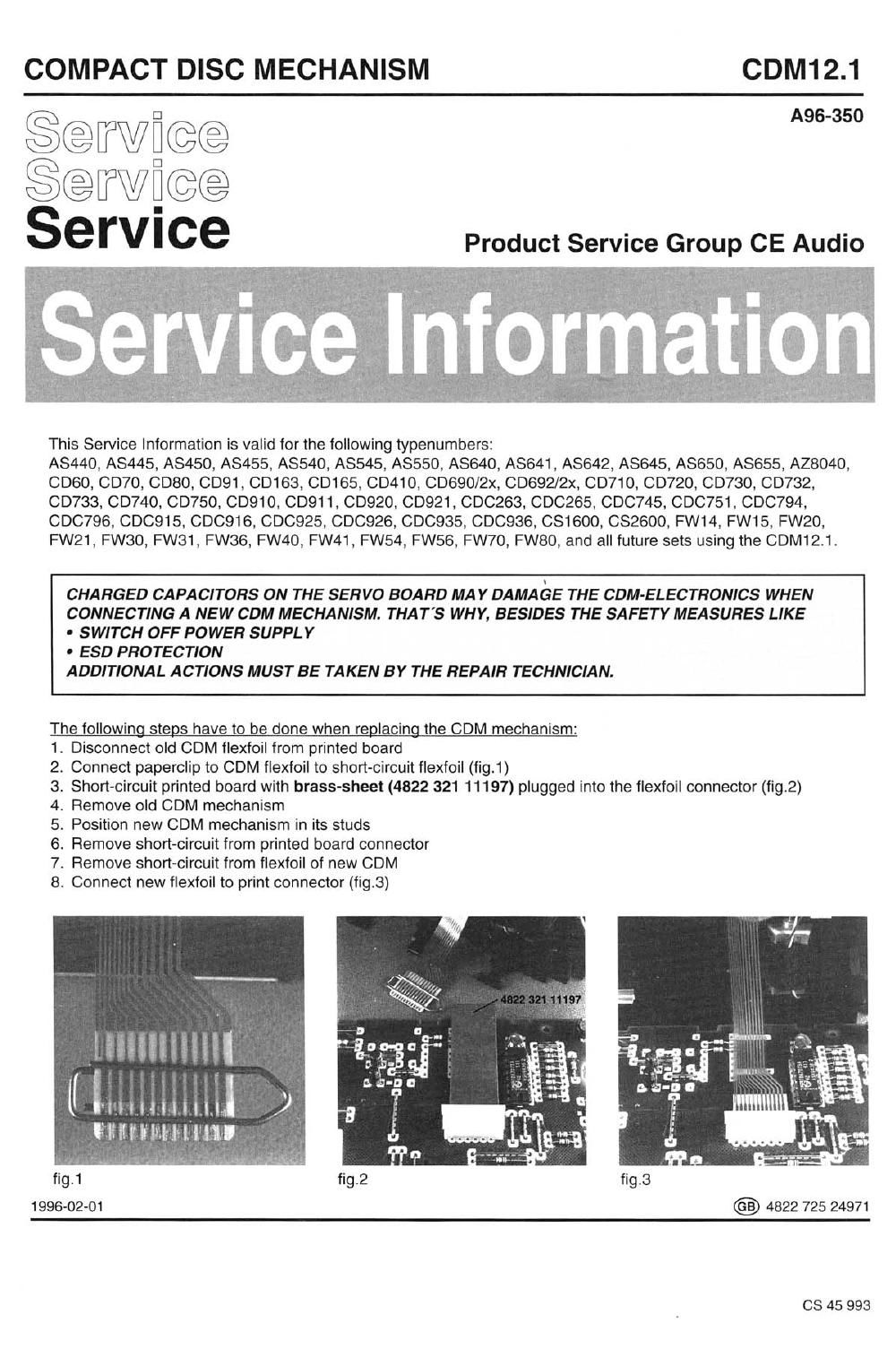
The followingsteps have to be done when replacing the CDM mechanism:
Disconnect old 00M flexfoil from printed board

Connect paperclip to COM flexfoil to short-circuit flexfoil (fig.1)

Short-circuit printed board with brass-sheet (4822 321 11197) plugged into the flexfoil connector (fig.2)
Remove old CDM mechanism

Position new 00M mechanism in its studs
Remove short-circuit from printed board connector
Remove short-circuit from flexfoil of new 00M
Connect new flexfoil to print connector (fig.3)

9°N¢WPP°E°9

~ 1;? (irfi,
ti't-tEI-t'f'lE'

\

Earnininfll ,1

Hillllt'wlltlll'tlll

fig.1

1996-02-01 4822 725 24971

CS 45 993