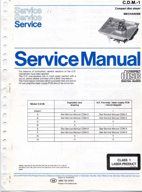
Philips cdm 1 service manual

This is the 26 pages manual for philips cdm 1 service manual.
Read or download the pdf for free. If you want to contribute, please mail your pdfs to info@audioservicemanuals.com.

Page: 1 / 26
left right
philips cdm 1 service manual

Extracted text from philips cdm 1 service manual (Ocr-read)


Page 2

SERVICING HINTS

In orderto prevent loose metal objects from getting in the
CD mechanism it will be necessary to see to a clean repair
station.

The objective can be cleaned with a blow brush.

The CD-mechanlsm is provided with self-lubricating
bearings and should thus NOT be lubricated.

Ensure that the player I: not resting on the shatt of the
turntable motor during repairs and measurements on the
bottom.

Servicing the RAFOC unit (= Radial and Focusing unit
pos. 81).

The RAFOC unit supplied by Service is the same one as in
CDM-O, In the CDM-t the bottom plate ofthis RAFOC unit
has been replaced by frame item number 503. If the
RAFOC unit is replaced, carefully an accurately perform
the following operations:

- Take the two flex PCBs out of the connectors on the
preamplifier PCB,

- Disassemble the defective RAFOC unit by removing
the 4 bolts Maxie mm and shaft item number 504.

- Remove shaft item number 504 of the new RAFOC
unit.
Pay attention to the 3 intermediate washers item
number 502 and spring washer item number 505. they
should assume the same positions after assemblyt

Loosen the 4 bolts M3x18 mm until the bottom plate
can be removed.

Do not remove bolts Maxis mm (they hold the new
RAFOC unit together).

- Mount the new RAFOC unit on frame 503.
Ensure that the 3 intermediate washers 502 and spring
washer 505 are positioned correctly before fixing shaft
item number 504.

- Check that the arm moves freely and the angle setting
as well (see check and possible adjustment of angle
setting).

- Forreplacingthelightpinitisnotnecessaryto remove
the RAFOC unit,
The light pin can be removed by turning it anti-
clockwise by means of an open-ended spanner of
12 mm and afterwards pulling it out of the arm.
During mounting. the light pin must be pushed into
the arm as far as possible, and turned clockwise.

Attention:

To prevent adluetmente from changing. NO SCREWS
OTHER then those mentioned above should be
loosened.

THE LIGHT PIN IS MUCH MORE SENSITIVE TO STA-
TIC CHARGE THAN A MOS IC. CARELESS TREAT-
MENT DURING SERVICING MAY REDUCE LIFE
EXPECTANCV DRASTICALLV. FOR THIS REASON
CARE SHOULD BE TAKEN THAT DURING SER-
VICING THE POTENTIALS OF THE AIDS AND YOUR-
SELF EOUAL THE POTENTIAL OF THE MECHANISM.

In the player chip components have been applied. For
insertion and removal of chip components see Fig.

GENERAL DISMOUNTING MOUNTING

VACUUM PISTON a g A PAIR OF TWEEZERS

SOLDERING 4822 395 V0092
mow \ .
99 WELLER g3

SOLDER Yw PY-H7

on A ,. sowsn
SOLDERING . 05 <5 mm
0" \ somenmc \ FRESSURE
SOLDER wrcx IRON
1322 321 40012 \
someewe nus semen a
u g A mm or rwaszsns : 3 sec/side . o 5 - n 3 mm
pwessune SOLDERING
HEATING I HEATING 6 IRON
x l
sowznmc mow
CHIF \ c
COMPONENT
SOLDIER SOLDER SOLDER wrcx :\ \ CLEANING EXAMPLES
~ come macx \
i-l p c a

% @i<&

SOLDERING

PRECAUTIONS
SOLDEFIING
IR N

O
IGHT
1
OFFER TRACK
SOLDERING
IRON
CHIF
COMPONENT

SERVICE PACKAGE

27 012cm
CS 98 647