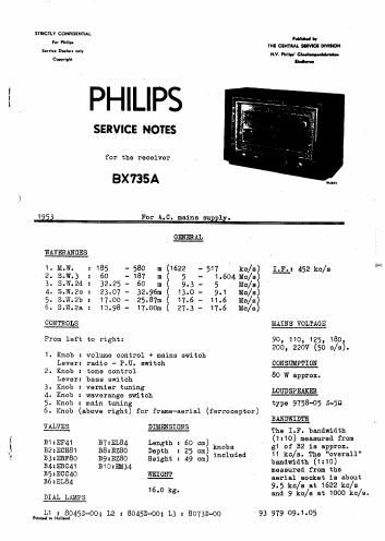
Philips bx 735 a

This is the 20 pages manual for philips bx 735 a.
Read or download the pdf for free. If you want to contribute, please mail your pdfs to info@audioservicemanuals.com.

Page: 1 / 20
left right
philips bx 735 a

Extracted text from philips bx 735 a (Ocr-read)


Page 2

- 2 _ Bx 735A

List of illustrations:

fig. RF. and oscillatorcircuit for each position of the waverange

switch.

fig.2: Trimming points on the dial.

figd: Cable drive for pointers, variable capacitor and. frame derial.
fig.4: Simplified diagram for tonecontrol and bass-switch 3K6.

fig.5: Push-pull output stage.

fig.6: Switch wafers.

figJ: Circuit diagram.

fi5.8: Wiring diagram (under)

fig.9: Wiring diagram (above)

fig.10: Maine-transformer.

CIRCUIT DESCRIPTION

A.

a.

R.F. Part

p.

Fig.1 shows for ever},r position of the waverange switch a simplifie
diagram of the 11.1. part.
Bandspread in the ranges S.W.2a, S.\'!.2'b and. S.W.2c is obtained by con-
necting condensers in series and. in parallel with the variable conden-
ser.

Iihe Vernier control is obtained by self-induction changes of the
coil $28 for the ranges S.W.2a, S.W.2h and S.W.20 and of the coil 535
for the range S.W.2cl.

The A-F. Part

The A.F. amplifier comprises 3 stages:

1. The pro-amplifier, 34, with tone control circuit.
2. The phase inverter valve, 35.

3- The push-pull output stage.

The AJ. signal obtained after detection is applied. via. 1131-332, 053,
1139 and 054 to gB4. The volume controls 331-232 and £54455 are mounted
on one spindle in connection with the physiological tone correction.

TONE CONTROL

Bass-switch fSKG 1515.4)

Connected between the anode and the grid of B4 is an inverse feedback
circuit some elements of which can be switched in and. out of circuit.
The working is as follows:

The impedance of the parallel connection 345-059 is greater for low
frequencies than for high ones, as a result of which the inverse feed-
back for the bass notes is reduced. The resistor R46 which can be con-
nected in parallel to R45 reduces the influence of the filter 345-659.
In the grid circuit of BA there is also 054, a small capacitor which
attenuates the bass notes reaching 534. This capacitor can be short
circuited with the bass-switch.

Summary of the 3 positions of 5K6:
1. Minimum bass notes: C54 in series with 053-2139
R46 parallel to 345-059