Philips bx 388 au

This is the 4 pages manual for philips bx 388 au.
Read or download the pdf for free. If you want to contribute, please mail your pdfs to info@audioservicemanuals.com.

Page: 1 / 4
left right
philips bx 388 au

Extracted text from philips bx 388 au (Ocr-read)


Page 1

STRICTLY CO PPRTTIAL .

For Philips Service
Dealers only. P s

/
x SERVICE NGTES
For the receiver

BX 388 A/U

112x: ~02.
1949. For LG. and D.C.maius.

For data, which are not mentioned here is referred to the notes
for the receivers BX 588 A or ET. 388 U.
The only difference is a. Foreign-Local switch, consisting out of;

5.. Switch . . A5 181 40.0
b. Two grommets 23 652 17.0
c. 067, 4700 pF 48 751 20/4117.

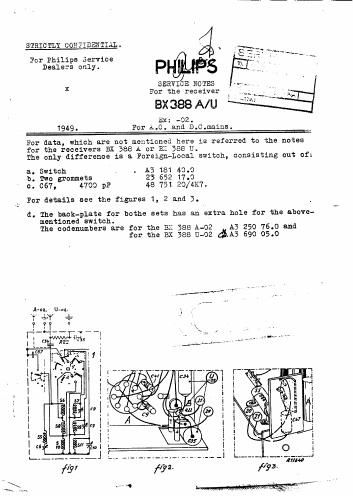
For details see the figures 1, 2 and 3.

d. The back-plate for bothe sets has an extra hole for the above-
mentioned switch.
The codenumbers are for the BL: 388 A42 A3 250 76.0 and
for the BX 388 (1-02 (3.10 690 05.0

Page 2

NM PHILIPS'
GLOEILAMPENFABRIEKEN Drive in the R.S. 917
EINDHOVEN 3:: see A/U'
SERVICE 15.4.49


When one
stable re
of the va;'
lowing way.

It has been found that as soc" , t _ is exposed
to mechanical vibrations, eit'we' ' 4 on the
cabinet 0: 0 rig to a quality ' ' it is apt
to turn 332:: e. little.
The Job can be done in three parts new
of the slip.

M anical "slip"
:4 the fol-

":o the extent

A. Re.;ove tLie spring washer nous.
If this does not have the ties
point 3.

B. Partly release the tension of the use sorings mounted in
the Philite driving drum by introcl
springs and cable loops a loo}: of .L'w 10 as. long. The
best material is a length of steel . The wire loops
must not be longer than 10 m. If tile rouble is still
not re.1edied follow the indications g van under 0,
which alteration has already been mad in a more recent
series of this receiver.

0. Remove the following parts:

1. Driving core and cable.
2. The breezet on which the Philit
ed, unscrewing this from the ch
The on the driving syinfle.
~qd roller mounted on tie v35. ale condenser.

\- brass wheels to left and right of the

condenser, unscrewing mess from the chassis.

ed 0' e drivigg shaft.
:e proceed to

1


mipfn
£33
(D

to be screwed onto the

over the drivii
Llly tap off the bras
and replace it by a
The spring washer an
be removed. and is not
t the driving shaft.
on a new arm and roller on the variable condenser
(33.5.51.
5. Again screw down. the bracket on union the Phi-
lite driving drum is mounts-u

use


After this has been done make the driv .
length. The cord loop is sh 'm 4 11; 4.- n mounting the
variable condenser set is to ma 3, ty (turned clock-
wise). Take care that the cord is lei. exactly shown in the
illustration .

core the right

m: a