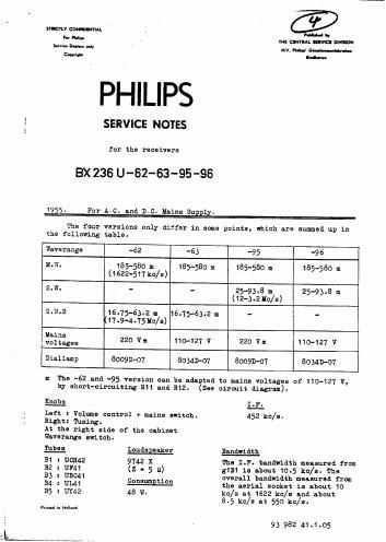
Philips bx 236 u service manual

This is the 9 pages manual for philips bx 236 u service manual.
Read or download the pdf for free. If you want to contribute, please mail your pdfs to info@audioservicemanuals.com.

Page: 1 / 9
left right
philips bx 236 u service manual

Extracted text from philips bx 236 u service manual (Ocr-read)


Page 2

Warning:

BX 236 U-62 ~53 -95 -96

lliimmig the receiver

hiring repairs or trimming when the receiver has been connected
to an LC. mains. a transformer with separate windings has to be used.
The chassis or the set may now he oerthed.

Mind the polerity connecting the set to n. 13.0. mains.

LF. circuits.

1. Volume control to muimum.
2. Tuning capacitor to minimum.
3. Waverenee switch to ll.w.

4. Connect a voltmeter via a trimming transformer to the connections

of the loudspeaker.

5. Screw the cores of the LF. handfilters out as far as possible.
6. Apply a modulated signal of 452 kc/s via a capacitor of 33000 pF

to 51 a! B1.
Trim for maximum output
4th LP. circuit SB
3rd LP. circuit S?
151: LF. circuit 55
2nd LF. circuit SS

7. Seal the cores of the LF- bendfilters.

R.F. end oscillator circuits.

Triming point 1 extreme left side of the dial.

Trimming yoint 2 extreme right side of the dial.

Set the pointer tc trimming paint 1 with the variable capacitor to

minimum.

1. Volume control to maximum.
2. Connect a voltmeter via. 3 trimming transformer to the connections

of the loudspeaker.

3. Apply all signals vie e normal dummy serial to the serial socket.

Version Weverenge Pointer en Modulated Trim for Remarks
switch trimming signal of max.
point output
-62 -63 lmr. 2 550 kc/s s14; $12 a
-95 -9s 1 1630 kc/s 623; on "Pm
-95 -96 3.11. 2 3.3 uc/s 54- 52 )
1 12.2 Ic/s 'ca ) "PS
-52 -63 s.w.2 2 5.11 uo/s 34- 52 )
1 18 uc/e 'cB ) "9"
Driving cord.

The path and length of the driving card are indicated in fig.1, the
Variable capacitor being set to maximum.

\_,. '