Philips ah 673 service manual 2

This is the 3 pages manual for philips ah 673 service manual 2.
Read or download the pdf for free. If you want to contribute, please mail your pdfs to info@audioservicemanuals.com.

Page: 1 / 3
left right
philips ah 673 service manual 2

Extracted text from philips ah 673 service manual 2 (Ocr-read)


Page 2

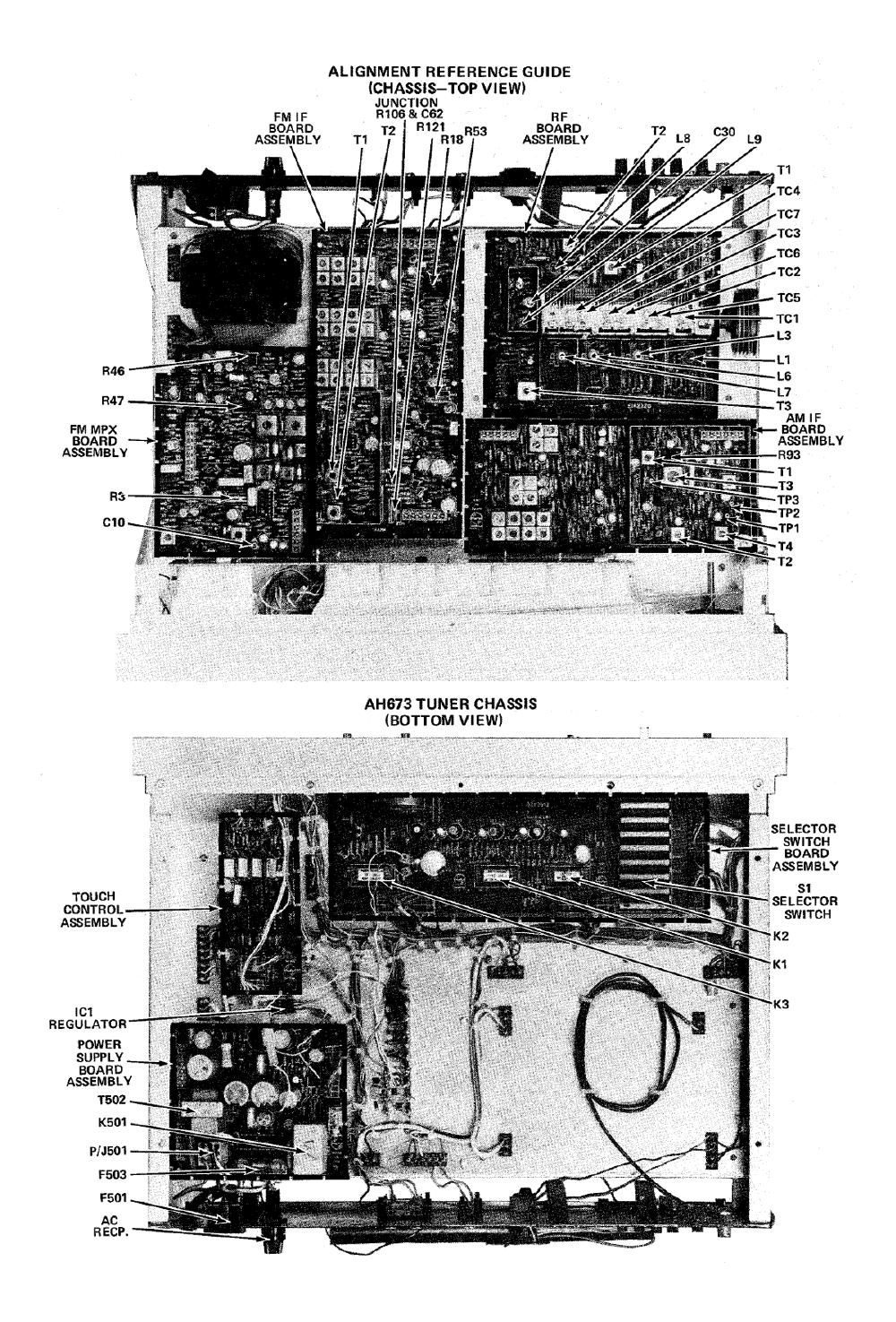
ALIGNMENT AND ADJUSTMENTS

CAUTION-BEFORE ATTEMPTING TO ALIGN THIS RADIO CHASSIS, READ PROCEDURE TO
ASSURE YOU HAVE AVAILABLE ALL TEST EQUIPMENT NEEDED.

Test Equipment Required:

AC VTVM

DC Meter

Oscilloscope

Distortion Analyzer

AM Sweep Generator

Freouencv Counter

Sound TechologyoModel 1000A FM Alignment Generator

Low Distortion (.05% or less) Audio Generator, with variable output.


AM IF'ALIGN ME NT


NOTE: Remove the Top and Bottom shields before attempting alignment. RENE adjust the 4-Pole and 8-Pole filters.

1. Using a sweep generator radiate a 455KHz RF signal to the AM antenna.
2. Connect an oscilloscope and meter to the junction of R90 and R84 (TP3).
3. Place the Selector switch in the AM "FIDELITY" position.

. Adjust T1, on AM IF board assembly, and T2, on RF board assembly, for maximum symmetry and output.
5. Relocate scope to the junction of R105 and R108 (TP2).
6. Adjust T4 for a symmetrical "8" curve.

7. Adjust T2 for maximum audio on the meter.

AM RF ALIGNMENT

. Radiate an RF signal generator to the AM antenna. (Output of generator should be as low as possible while maintaining
usable indication on the meter).

. Connect an AC VTVM to the Fixed Output jacks.

. Place the Selector switch in the AM "NORMAL" position.

. Set the RF generator for a 600 KHz signal and place the pointer to the 600KHz indication on the dial scale.

. Adjust L8, T1 and the AM antenna rod for maximum deflection on the meter.

. Reset the RF generator for a 1400KHz signal and place the pointer to the 1400KH2 indication on the dial scale.

. Adjust trimmers TCS, T06 and TC7 for maximum deflection on the meter.

. Repeat steps 4 thru 7 until no further improvement can be obtained.

-_ - 1 I

AM TUNING METER ADJUSTMENT 4"
Radiate a 5KuV/m AM RF signal with 30% of 6KHz modulation to the AM antenna.
Place the Selector switch in the AM NORMAL" position.

Connect an AC VTVM to the Fixed Output jacks.

Tune the radio to the signal by tuning for minimum audio.

While Eating the tuning meter, adjust T4, on AM IF board assembly, for "center".

9195019?

AM OUTPUT-LEVEL ADJUSTMENT


NOTE: The Top cover of the AM IF board assembly must be removed for this adjustment.

1. Radiate a 50KuV/m AM RF signal with 30% of 1KHz modulation to the AM antenna.
2. Place the Selector switch in the AM "FIDELITY" position.

3. Connect an AC VTVM to the Fixed Output jacks.

4. Ad'ust R93_for an 300mV Ojtput.

._l

1OKH-z-FILTER ADJUSTMENT

-f-


NOTE: It is very critical that 10KHz :t- 2Hz must be obtained for this adjustment.

1. Radiate a 50KuV/m AM RF signal with 30% of 10KHz modulation to the AM antenna.
2. Place the Selector switch in the AM "FIDELITY" position.
3. Connect an AC VTVM or scope to the Fixed Output jacks.
4. Place the 10KHz Filter switch in the "ON mode and adjust T3 for null, minimum output (approx. 40dB down).