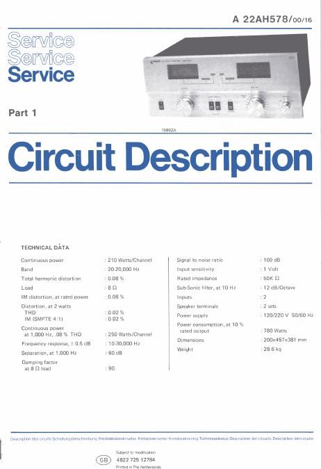
Philips ah 578 service manual

This is the 22 pages manual for philips ah 578 service manual.
Read or download the pdf for free. If you want to contribute, please mail your pdfs to info@audioservicemanuals.com.

Page: 1 / 22
left right
philips ah 578 service manual

Extracted text from philips ah 578 service manual (Ocr-read)


Page 2

FREQUENCY-RESPONSE

to 50 too 500 IK 5K 3K 50K

Hz

§§§

men ooreur IN mm:
8

LOAD IMPEDANCE 7 B
THD 7

OUTPUT POWER VS.
HARMONIC & INTER MODULATION DISTORTION

02

SPEAKER LOAD 7 sol-ms
BOYH CHANNELS DRIVEN

or
006

005

002

INTER MODULATION AND most

0.01

Watt

POWER BANDWITH

Fig. 3

CHASSIS IDENTIFICATION

A620 -- JElli.
Basic chassis Chassis version
series within the series

INSTRUCTIONS FOR SERVICING AND REPLACING
PARTS

Driver and output transistor replacement

Since transformerless quasi complementary output
circuitry is utilized in this chassis, extreme care should
be exercised when servicing or replacing the transistors.
It is imperative that the transistors be isolated from the
heat sink by means of a mica insulator coated on both
sides with Dow-Corning DC4 silicon grease, or equivalent

When replacing a driver or output transistor, make
certain the replacement transistor has the same beta
range (i.e., Orange or Red) as the defective transistor.
The beta range of the transistor is indicated by a red or
orange dot (or lettering) on the top of the case. Failure
to replace a defective driver or output transistor with
one having the same beta characteristics could be
detrimental to the performance of the power amplifier.

After servicing or replacing one or more of the output
transistors, the Quiescent Current Adjustment must be
performed in the affected channel. Misadjustment of the
output transistors will cause crossover distortion and
possible premature failure of the.output transistors.

CS 62 565

AIA

Important electrical

Important mechanical
change

AA = Original production
B etc. = Production change codes

Driver board assembly service position

For ease in troubleshooting and servicing the compo-
nents located on the driver board assembly, disassemble
the chassis as follows:

1. Remove the cabinet top (1) and bottom pan from
the power amplifier.

2. Remove the four safety screens from the large heat
sink to which the driver board assembly, that is to be
serviced, is mounted to.

3. To obtain additional slack for the wires connected to
the thermal switch (mounted on the large heat sink),
remove the wires from the nylon tie located on the
bottom of the chassis.

4. Remove the eight screws securing the large heat sink
to the chassis. The driver board assembly/heat sink
can now be removed from the chassis by gently
rocking it back and forth while, at the same time,
lifting it up and out of the chassis. When the driver
board assembly/heat sink is released from the chassis,