Philips 834 b service manual

This is the 2 pages manual for philips 834 b service manual.
Read or download the pdf for free. If you want to contribute, please mail your pdfs to info@audioservicemanuals.com.

Page: 1 / 2
left right
philips 834 b service manual

Extracted text from philips 834 b service manual (Ocr-read)


Page 2

110

Service Engineer Supplement to the Broadcaster

A ugurt, 1934

PHILIPS BATTERY
834B (Cont.)

Quick Tests.fiTlicse consist of routine
tests of the valves with observation of the
clicks" produced by making the connec-
tions for the different measurements.

Removing Chassis.-Undo the knobs
(grub screw) and remove the four holding
screws by inserting a lon screwdriver
through the holes in the ottom of the
cabinet. Unsolder the earthng lead to the
speaker and lift the chassis out The LS.
leads are sufficiently long, and the chassis
will stand on either end.

General Notch-The bias resistances,
R12 and HIS, consist of small lengths of

VALVE READINGS
No signal.
Type. Electrode
1 PMJZA . anode
sueen . so
2 PMIZA . anode 122
3138921 54-
3 PMQDX anode 52 1.85
4 PMZZA . anode 123 .7
aux. grid 125 2
5 PMIHL ... anodc 10 1
' With moderate signal, 15v., .02 mu.

coiled resistance wire soldered to the valve
sockets and to chassis.

The action of the control valve, V5, is
straightforward. With the valve in position
the current taken b V4 depends on the
stren th of the sigma , and fluctuates above
and ielow 2.5 me, but with the control
valve removed the pointer swings slightly
above and below 5.3 ma. With no signal
and controlled, the V4 current is .7 m.a.,
but with V5 removed the current is 5.3 ms.

The wiring is easily followed and, with the


CONDENSERS
Purpose. Mm
1 l Decoupling H.1. to HF. valves .1
2 Decoupling HE. to V3 anode .1
3 Decoupllng V4 grid . .25
4 Across part of 1LT. ptr .1
6 Series serial 00nd.
10 . .
11 F. transformer . f
LWl . .00085
12 Part ofcontrolvslve grld circuit .01
13 LF. feed to valve grid circuit .008
14 vs anode by-pass .002
17 HI. by-pass from V4 grid 00005
18 Between V] + filament and LT.
20 . . .1
21 + filament and L
neg. ... .l
22 Decoupling V1 screen .1

aid of the circuit diagram, the anode and
grid circuits can be traced easily. As usual
with these Supurrinductance sets, the trim-
mers should not be disturbed.

Replacing Chassis.--See that the
rubber rings are in position and lay the
chassis on them. Place the earthing plate
for the foil screen under one of the rear
supports with the convex end downwards,
end replace the holding screws. Resolder
the earthing lead to the speaker, clip the
LS. leads, and replace the knobs.

RESISTANCES
n. Purpose. | om
1 Decoupling 1LT. from ELF. 00
nodes.
2 PlrtofH.T.snd G.B.control tr. 1 meg.
3 Part ofH.T.nndG.B.contro ptr. .64 men.
4 Part MELT. and (:r.B . controlptr. l meg.
5 PurhotIIJJnd G,E.conmlptri .l or .16
meg.
6 V1 filament. volume control 20
7 Across iec. of semilperiodir 1 64 meg.
transformer.
8 vs grid leak 1 1 meg.
9 v5 gridleuk 21mg.
10 H3. stopper V4 grid 2 men.
11 H.112 stopper V4 grid 2 meg.
12 Fixed res . in V1 fll. 1.26
18 Fixed resist. in v2 fll. 1,25
14 Decoupling HE. to V1 screen 40.000
15 Decoupling H.T. to V3 on 40,000
. and v2 screen.

AlAZE

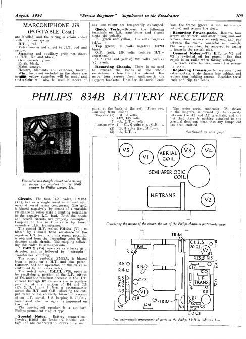
Two H.F. amplifiers, detector and pmimlc output values are employed in the Philips 8343 receiver.

cansumplion of the penlodc i0 snil [he volume.

The fifth valve is used to adjust the

The Detector Stage (Continued from page 95)

diode load resistance, and the LR coupling
condenser is connected between the slider
and the rid of tho triode section which has
its own xed grid leak. Either method may
include an H.F. stopper, R4, in the grid
lead of the triode section.

\Vheu reconnecting the components alter
dismantling any of them, care should be taken
to ensure that the diode D.C. circuit is con-
tinuous to cathode through a load resistance
(and bias resistance in the. diagram) and that
the condenser (72 is not shortrcircuited.

Tn sets which do not employ A.V.Ci a good
test of the detector lies in connecting a, high-
resistance meter (with a total resistance of
100,000 ohms or more on the scale used) be-
tween the points A and B,

When rectification is taking place a de-

flection oi from two to nine volts will be ob-
tained from a local station on an oscillator.
This represents a very small deflection of
the average good servme meter, but it is
sufficient evidence oi rectification.

When no such reading is obtained, a test
valve should be tried, and if this fails the
H.F. side of the set should he examined.
One infallible test of the valve is by con-
necting the dummy aerial of the modulated
oscillator (tuned to the correct 11.) to the
diode anode and to chassis, and noting
whether or not the valvc is rectifying the
S] 1134 .

n testing doublerdiode triode valves it is
sufficient to take the emission of the triode
section. This will tell whether or not the
cathode has lost its emission.

SEPTEMBER SERVICE
ENGINEER."

The September issue of SERVicE ENGI-
NEER will contain reviews of the following :

Atlas-758 mains set.

Gasser-455B battery three.

Ferranti-Lancastria portable.

G.E.C.-A.V.C. 5.

Halcyon-6701 'Lvalve A.C.

K.-B.-A.C. Pup.

MallardMMB. Threc.

Philips-588 A superhet.

R.G.D.-~Radiogram.

Ultraw 22.

All correspondence relating to SERVICE
ENGINEER should be addressed to THE
BROADCASTER AND WIRELESS RETAILER,
29, Bedford Street, Strand, London,
7.13.2. 'Phonc Nor: Temple Bar 2/168.