Philips 805 a service manual

This is the 2 pages manual for philips 805 a service manual.
Read or download the pdf for free. If you want to contribute, please mail your pdfs to info@audioservicemanuals.com.

Page: 1 / 2
left right
philips 805 a service manual

Extracted text from philips 805 a service manual (Ocr-read)


Page 1

,__. 1

PHILIPS
305A, 805x

Four-valve, plus rectifier. three
waveband super/let. A cathode-my
tuning indicator is incorporated and
provision made for the connection
of a [71110017 and law impedance
extra speaker. Model 805A is
for operation from AC mains
supply 100-260v. 50-60 cycles.
Model 805X ittcarporates the same
chassis, but is supplied with a
Philips 7882C Converter, and is
suitable for DC mains of 100-145v
and ZOO-250v. It is a simple matter

to disconnect the converter so that .

the instrument may be operated from

AC. Manufactured by Philips

Lamps, Ltd., Service Department.

74 - 94, Cherry Orchard Road,
Croydort.

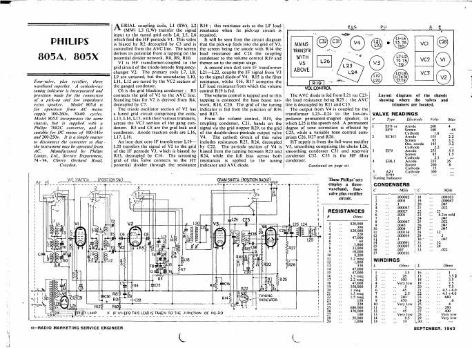
AERIAL coupling coils, Ll (SW), L2
(MM L3 (LW) transfer the signal
input to the tuned grid coils L4, L5, L6
which feed the HF pentode V1. This valve
is biased by R2 decoupled by C3 and is
controlled from the AVG line. The screen
derives its potential from a tapping on the
potential divider network, R8, R9, R10.

V1 is HF transformer-coupled to the
grid circuit of the triode-hexode frequency-
changer V2. The primary coils L7, L8,
L9 are untuned, but the secondaries L10,
L11, L12 are tuned by the VC2 section of
the ganged condenser.

C6 is the grid blocking condenser : R3
connects the grid of V2 to the AVC line.
Standing bias for V2 is derived from R4,
decoupled by C7.

The triode oscillator section 01' V2 has
a luned grid circuit comprising the coils,
L13, Ll4, L15, with their various trimmers,
across the VCS section of the gang con-
denser. RS and C8 are the grid leak and
condenser. Anode reaction coils are L16,
L17, L18.

An iron dust core IF transformer L19-
L20 transfers the signal of V2 to the grid
of the IF pentode V3, which is biased by
R13, decoupled by C16. The screening
grid of this italve connects to the HT
potential divider through the resistance

R14 ; this resistance acts as the LF load
resistance when the pick-up circuit is
required.

It will be seen from the circuit diagram
that the pick-up feeds into the grid of V3,
the screen being the anode with R14 the
load resistance and C24 the coupling
condenser to the VOIUme control R19 and
thence on to the output stage.

A second iron dust core IF transformer
L21-L22, couples the IF signal from V3
to the signal diode of V4. R15 is the filter
resistance, whilst R16, R17 comprise the
LF load resistance from which the volume
control R19 is fed.

The volume control is tapped and to this
tapping is connected the bass boost net-
work. R18. C201 The grid of the tuning
indicator is fed from the junction of R16
and R17.

From the volume control, R19, the
coupling condenser, C21, hands on the
signal via the grid stopper R29, to the grid
of the double-diode-pentode output valve
V4. The cathode circuit of this valve
includes resistances R23, R24, decoupled
by C22 The pentode section of V4 is
biased from the tapping between R23 and
R24, while the full bias across both
resistances is applied to the tuning
indicator and AVC diode.

A e
.s. W '
nns @@ .-
TRANSF'R , ,
\X/ITH "
V. @
ABOVE . v93
1219 \
VOLCONTROL

The AVC diode is fed from 1.21 via C23v
the load resistance being R25 ; the AVC
line is decoupled by R11 and C13.

The output from V4 is coupled by the
transformer L23-L24 to the low-im-
pedance permanent-magnet speaker, in
which L25 is the speech coil. A permanent
degree of tone correction is eflected by
C25, while a variable tone control com-
prises C26, R27 and R281

HT supply is from the full-wave rectifier
V5, smoothing comprising the choke L26,
smoothing condenser C31 and reservoir
condenser C32. C33 is the HF filter
condenser.

Continued on page vii

R
LAMP

A vglL WATCH (Posmon 5w) GRAM swncu (vosmou RADIO)
.9? ... - ______________________________________________ r-'-_ _ _ _

\

R8
R

R

* IF V1=EF9THIS LEAD IS TAKEN TO THE JUNCTlON OF [18-119

TUNING

m4 IN Dicrroa

' ' C

These Philips sets
employ a three-
waveband, four-
valve plus rectifier
circuit.

RESISTANCES
R Ohms

vl-RADIO MARKETING SERVICE ENGINEER

L

L

Layout diagram of the chassis
showing where the valves and
trimmers are located.

VALVE READINGS
V Type Electrode

Volts

he

so
.

1:

Screen 95
05121 anode
Cathode 2 2
Anode
Screen 85
Cathode 2.1
Anode
Screen
Cathode Is
Cathode

Tuning Indicator

CONDENSERS
C Mfds

.000082 18
.OODI

PP!
NNN

l

N
e.
1'.

_.u.

mun

4 EBLl

5 All

. 1
1000047 2|
.00027 22

., 1047
17 .. .oomos
WINDINGS
Ohms

' ' Very low
5

' Very low

.. 45
Very low
. 8.5

19

SEPTEMBER. 1543

Very low'

Page 2

v, , . a".-. . c...

33
g
i

' PILOT
"TWIN MIRACEE ..

Four-valve, plus rectifier. Irnm»

portable super/let covering two

wavtbands am] for operation from

all-dry batteries or AC or DC

mains. Made by Pilot Radio, Ltd.,

3143, Park Royal Road, London,
NW 10.

INTERNAL frame aerials L2 (MW),

L4, (LW) may be coupled to an external
aerial. if desired. via C1 and coupling coils
L1, L3. L2 and [A are tuned by VCl and
the signal passed direct to the grid of the
heptode frequency changer V1.

The oscillator section of this valve has a
grid circuit LS (MW). L6 (LW) tuned by
VCZ ; L7 is the reaction winding fed from
the oscillator anode by means of HF choke
L8, and C4.

The IF transformer, L9~L10, couples
the IF signals to the grid of the IF pentode
amplifying valve V2. A second IF trans-
former LIl-LIZ hands on the signal to
the single diode-triode valve V3.

R7 which feeds the triode section of V3.

The LF signal is coupled from the load
resistances by C8 to the volume control

The DC potential across the load resist-
ances is fed via R10 to the grid circuit of
VI and V2 as AVC.

V3 is resistance capacity coupled by R3,
C10 and R8 to the pentode output valve
V4. This is transformer coupled by L13-
L14 to the permanent-magnet speaker in
which 1.15 is the speech coil.

Fixed tone correction is eflected by C12.
while bias is derived from the resistances
RII, R12 in the HT circuit (the latter on G
mains operation).

The power supply on battery operation a
is derived from the all-dry HT and LT
combined battery which plugs into a
socket and is left permanently connected.
Switches 53 and S4 are ganged and when
these are switched to the ON position the
valve filaments are in parallel across the
LT section of the dry battery.

If the mains lead is then plugged into a
supply socket, current flowing through the
relay winding L17 energises the relay
magnet and pulls the contacts over for
ACADC operation.

The HT positive line is then switched
over from the battery to the smoothing
circuit comprising L16, C13, C14 which is
fed from a tap on the line-cord R16. The
rectifying valve V5 has its heater fed from I

to

HT negative
biasing.
from the HT line. the current flowing
through V4, V3 and V2 in parallel, through
VI and R13 in parallel, and so through the
indicator lamp and R14 to the HT negative.
The indicator lamp lights up on mains but
not on battery.

the mains via the line-cord R16, and the
HT negative line from the anode is taken
via the relay contacts through the indicator
lamp, R14 to the chassis.

The grid circuit of V4 is connected to
via R12 for additional
The filament current is taken

ANGING

IF Circuits-Inject a 451 kc signal via
.1 mfd condenser to the grid of V1.

Adjust T1, T2, T3 and T4 in that order

for maximum reading on output meter.

MW Bands-Check that pointer is

horizontal with gang at maximum. The
output from the oscillator may be coupled

the nerials by a turn of wire round the

outside of the cabinet.

The trimmers are accessible through

the removable panel in the base of the
cabinet with the battery removed ; thus
the receiver must be ganged when opera-
ting from the mains.

Switch to MW, tune receiver to 200m,

and inject a 200m signal. Adjust TS and
T6 for maximum output.

Continued in end column

Two views of the Pilot chassis
identifying the major components

and showing trimmer positions.

VALVE READINGS

V Type
I IA7EG
2 INSG
3 IHSG
4 tcseo
25250

Ma:

Electrode Vail:
Anode 75
05c. anode 78
Screen 37
Anode 75
Screen 75
Anode 1 5
Anode 78
Screen 80

.3
I.

3

.6

.8
.1
.02
4.7
2.0

Above figures refer to battery operation.
Values are slightly higher on mains.
Indicator Lamp: 6.3 y. .15 amp., M.B.C.
Battery : EWFRtEdy All-dry 3.

ins i

L1 L2

L3 L4 M 5
SI T9
i 4=


RELAV.
WINDING


Feature of

the

circuit is the relay
which automatic-
ally switches over

to battery or
mains according
R to which form of
16 supply is con-
nected.
I
i CONDENSERS
06 C

SEPTEMBER, 1943

mmawN-ommqmmbuup-

PHILIPS own... 1...... page .1

IF Clrcuits.~The wavelength switch at
MW. variable condenser at minimum and
volume control at maximum, apply a
signal of 470kc to control grid of the V2.
Detune circuits by placing across them a
20,000 ohms resistance in series with an
0.1 mfd condenser and trim for maximum
output as shown in the following table :7-

L19 L20 L21 L22
- - Detune Tune Ist
~ - Tune 2nd Detune

Detune Tune 3rd Detune -

Tune 4th Detune Detune
Keep output low to avoid operating the
AVC. '

. SW Band-Set gang to a Philips 15"
ig. Trim T1. T2, and T3 for maximum
output at me,

MW Band-Set gang to the 15° jig.
Trim T4, T5, and T6 for maximum output
at 1,442kc.

Tune gang to 545kc. Trim T7 for
maximum output on a 54Skc signal.

Reset gang to 15° jig and retrim T4 for
maximum output at 1,442kc.

LW Band-Set gang to the 15° jig.
Trim T8, T9, T10 at 405kc.

Tune variable to 160kc. Trim T11 for
maximum output on a 160kc signal.

Reset gang to 15° jig and retrim T8 for
maximum output at 405kc.

Continued from column 3 .

Inject and tune in a 500m signal and
adjust T7, while rocking gang.

LW Band.-Switch to LW, tune
receiver to 1,200m and feed in a 1,200m
signal.

Adjust T8 and T9 for maximum output.

Inject and tune in a 1,900m signal and
adjust Tit) for maximum output, while
rocking gang. <1

WINDINGS.

L Ohms 1. Ohms
I .1 10 6.5-
2 1,5 11 7.5

3 .2 12 4.5

4 21 :3 430

5 3.5 l 14 .

5 5.5 i 15 . 3

7 as i 16 r 200

8 no , 17 190

9 .. .. s. .

RESISTANCES

R Ohms I R 01ml:

1 56.000 i 9 TTFEI
2 2,200 10 35 mg
3 l meg 11 1.2.00

4 220,000 , 12 2,200

5 47,000 I I3 25

o 2.2 meg I I4 50

7 2 meg , 15* 700

a 33 meg , 16? 620

(tapped at 100)
When 1D5 valve used, RIS and R15A=
1.500 ohms tapped at 700 ohms.
t 910 ohms for IDS valve untapp ed.

FIADIO MARKETING SERVICE ENGINEERWII