Philips 797 a service manual

This is the 2 pages manual for philips 797 a service manual.
Read or download the pdf for free. If you want to contribute, please mail your pdfs to info@audioservicemanuals.com.

Page: 1 / 2
left right
philips 797 a service manual

Extracted text from philips 797 a service manual (Ocr-read)


Page 1

38

Broadcaster Service Mans Manual

' October, 1936

PHILIPS 797A ALL-WAVE SET

ROUTE-A five-valve AC. mains

/ superhet operating on short waves
from 16-50 metres and on the usual
medium and long wavesl

Aerial signals are fed to V1, the ire
quency changer, through an inductively
and capacitatively coupled bandpass
filter and a small resistance in series
with the grid to cut out parasitic oscil-
lation on short waves.

Signals are fed to V2, an H.F. pentode,
through an LF. transformer tuned to
128 kci The coupling between the wind»
ings of this transformer is manually
variable, and is ganged with the tone
control so that at the position of maxi
mum selectivity the reproduction of the
highest frequencies is at maximuml

A tuning indicator is connected in the
anode lead of this valve.

The output of VZ is passed, m'a a. second
I.Fl transformer. with fixed coupling to
V5, 3 double-diode triode, which is
volume controlled by R15. A fixed cou-
denser C21 is connected in series with
the slider and brought into operation by
depression of the volume knob.

One diode of V3 is used to supply
A,V.C. bias to the preceding valves in the
orthodox manner.

The LF. output of V5 is passed through
a resistance and capacity stage to the
output pentode V4, which is tone con-

l; =TUNE

WC
' cu

TONE&SELECTIVITY [HWOLUME

M

Audioseopie reproduction, Adapto-
visor dial, automatic two-speed
tuning, and linger-tip silencing are
among the features oi the distinctive
Model 797A live-valve all-wave super-
het marketed by Philips Lamps Ltd.

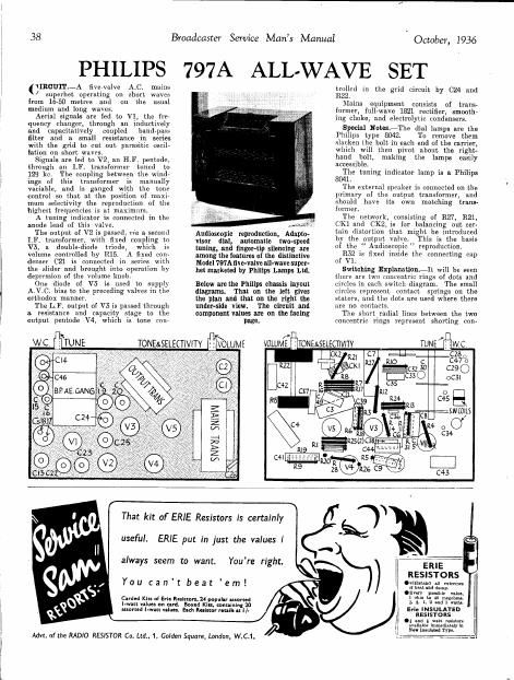
Below are the Philips chmis layout

diagrams. That on the left gives

the plan and that on the right the

under-side view. The circuit and

component values are on the lacing
page.

SNVHl SNIVW

pl
VOLUME ITONELSELECTIVITY

trolled in the grid circuit by 024 and
RZZ.

Mains equipment consists of trans-
former, full-wave 1821 rectifier, smooth-
mg choke, and electrolytic condensers.

Special NotesiThe dial lamps are the
Philips type 8042. To remove them
slacken the bolt in each end of the carrier,
which will then pivot about the right-
hand bolt, making the lamps easily
accessible.

The tuning indicator lamp is a. Philips
8041.

The external speaker is connected on the
primary of the output transformer, and
should have its own matching trans-
former.

The network, consisting of R27, R21,
CKl and 0K2, is for balancing out cer-
tain distortion that might be introduced
by the output valvei This is the basis
of the Audinscopic " reproduction.

R52 is fixed inside the connecting cap
of V1.

Switching Explanation-It will be seen
them are two concentric rings of dots and
circles in each switch diagram, The small
circles represent Contact springs on the
stators, and the dots are used where there
are no contacts.

The short radial lines between the two
concentric rings represent shorting con-

TUNE], ,wc,

cze
c4700

C29 0

oCSI

0
C45
Sit/(OILS

Advt. of the RADlO RESISTOR Co. Ltd.. 1, Golden Square, London, W.C.1.

That kit of ERIE Resistors is certainly
useful. ERIE put in just the values I
always seem to want.
You cant beat em!
Carded Klu all Erie Rfilsmn. 24 popular Blamed

Boxed Kin. containing 7.0
assorted l-wan urn-st sigh Rumor reuill n 1/-

l-wan values on card.

Youre right.

- l
Erin INSULATED
RESI 570 R5
l Cl mi 1 mm resistor-
} sv-llablt immediately in
new mom Type.

ERIE E:
RESISTORS l
.wltlnund All extreme-
0 but md dump.

.Evary gamble Valu-
1 ohm u: 40 mgohm.

l. l, i, u Ind 3 mm

Page 2

October, 1936
PHILIPS 797A CIRCUIT AND COMPONENT VALUES

Broadcaster Service Mans Manual

DlCATOR

An explanation of the switching in the Philips circuit is given iii the text matter.

the Radio position.

39

72R;

Switches A and B are shown in


VALVE READINGS

No signal. Volume maidmum. 200V.
A.C.ma.ins
V Type. Electrpde. Volts. Ma.
Mullard F04 Anode 260 2.2
Met (7) .. Screen 70 2
056. 7D 5
anode.
Mullard VPeB Anode... 240 6.5
2 Met.(7i Screen 150 2.3
Mllllzrd TDD4 Anode... 70 1.
3 Met (7) .. .
Mullard Pen. Anode... 250 34.
A (7) Screen 260 3.9
5 Philips 1821 Filament 285 -
5 (4)

Where there is a solid

tacts Oll the rotor.
line Joining two or more of these short

radial lines, the shorting contacts
actually connected together.

The dotted arcs show that adjacent con.
tacts are shorted together (not permaiir
ently, but according to the position of the
rotor).

The switches are shown in the open
position. They work in a clockwise direCA
tion. the order of operation being : short,
medium and long waves, gramophone.
With each new position, of course, all the
shorting strips move along one set of con-
tacts clockwise.

Removing Chassis-Practically all the
work necessary on this receiver may be
done without removing the chassis by

are

RESISTANCES CONDENSERS
h. Purpose. l Ohms Mfd.
1 V1 use. anode and screen de- 1 H T. smoothing 32
coupling 10,000 2 H T smoothing . 32
3 V3 anode decoupling .. 50,000 3 V3 cathode bias shunt 25
4 V1 cathode bias potentio- 250 4 V4 cathode bias shunt .. 25
meter. 5 V1 030. anode and screen (19- .1
5 V2 cathode bias coupling.
(5 V3 bias network 6 V2 anode decoupling .l
7 V8 bias network 7 V3 anode decoupling .5
8 V3 bias network 8 V1 cathode bias shunt .05
9 V4 cathode bias 0 V2 Cathode bias shunt .1
10 V1 A V c. decoupling 21 Mutiny; .1
11 V1 050. grid leak ... 26 Mains aerial .. .0005
12 u cdecoupling 28 Band pass coupling .0001
13 A.1V C iode load 20 V1 A. V. C decoupling .010
14 Part demod. diode load 30 Bund- -pnss coupling. .026
15 Volume mntiol .. 31 Short-wave coupling 000016
16 V3 series grid 32 Padding .00065
17 V3 grid leak 33 Padding .001375
18 V3 anode lead 34 V1 oscillator grid .. .0001
19 V4 grid leak. 35 VI A. V C. decoupling .1
20 V4 grid stopper , 30 A. V. C. diode coupling .00001
21 Audinscopic tone filter 37 L F coupling. .01
22 Tone control .. 38 H. F. by- pass .0001
39 Anode shunt.. .0004
2-1 V2 A.V.C. decoupling 40 L. F. couplini'n: .02
25 V2 semen decoupling 41 Pentode compensating .004
26 V4 screen decoupling 42 Tone circuit. .005
27 Audioscopic tone filter 43 V2 A V C. decoupling .1
23 V4 grid stabilise! 44 72 srreen decoupling .1
31 V1 cathode bills potentio- 45 Ysc. regeneration control .000002
meler, 47 Image suppressor .00002
32 V1 gzid stabilise: 49 Speech LF. coupling 00025

taking the fibre board from underneath the
Cabinet. This is secured by four screws.

Should it he found necessary to remove
the chassis, the' procedure is as follows:
Remove the tour knobs from the front of
the cabinet (the two large knobs have two
grub screws each) and the four bolts from
undeineath the cabinet.

Raise the scale assembly to the limit of
its travel, release the dial lamp bracket

tioiiiits securing bolts, and holding the
Bowden Wire slncken pointer screw.
Next free the cable to the wave- change
indicator and completely unscrew the
hollow adjustment screw. Unscrew the
two slotted nuts on either side at the
bottom of the scale and remove the copper
strips. The scale may then be removed,
This will leave the bracket supporting
( Continuedgon page 47.)