Philips 785 ax service manual

This is the 2 pages manual for philips 785 ax service manual.
Read or download the pdf for free. If you want to contribute, please mail your pdfs to info@audioservicemanuals.com.

Page: 1 / 2
left right
philips 785 ax service manual

Extracted text from philips 785 ax service manual (Ocr-read)


Page 1

4o

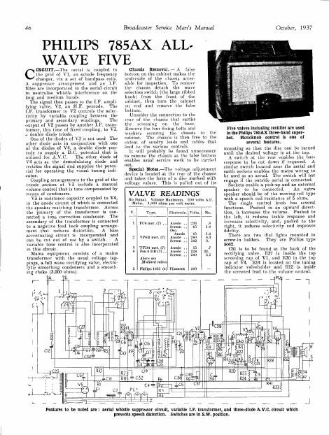
PHILIPS 785AX ALL-
WAVE FIVE

the grid of V1, an octode frequency

changer, via a set of bandpass coils.
A suppressor arrangement and an 1.F.
filter are incorporated in the aerial circuit
to neutralise whistle interference on the
long and medium hands.

The signal then passes to the LF. ampli
tying valve, V2y an H.F. pentode. The
[.F. transiormer to V2 controls the selec-
tivity by variable coupling between the
primary and secondary windings. The
output of V2 passes by another IF. trans-
lormer, this time of fixed coupling, to V3,
n double diode triode.

One of the diodes of V5 is not used The
other diode acts in conjunction with one
of the diodes of V4, a double diode pen-
tode to supply a DC. potential that is
utilised for A.V.C. The other diode of
V4 acts as the demodulating diode and
lectifies the signal and supplies the poten-
tial for operating the visual tuning indir
cator.

Coupling arrangements to the grid of the
triode section of V5 include a manual
volume control that is tone compensated by
means of condensers.

V3 is resistance capacity coupled to V4,
in the anode circuit of which is connected
the speaker matching transformer. Across
the primary of the transformer is con-
nected a tone correction condenser. The
secondary of the transformer is connected
to a negative feed back coupling arrange-
ment that reduces distortion. A bass
accentuating circuit is incorporated and
can be cut out of use by a. switch. A
Variable tone control is also incorporated
in this circuit.

Mains equipment consists of a mains
transformer with the usual voltage tap-
pings, a full wave rectifying valve, electro-
ytic smoothing condensers and a smooth-
ing choke (5,000 ohms).

cIBGUIT.-The aerial is coupled to

cs
RI
' c2

Broadcaster Sewice Mans Manual

chassis Removal.~A false
bottom on the cabinet makes the
underside of the chassis acces
sible for inspection. To remove
the chassis detach the wave
selection switch (the large ribbed
knob) from the front of the
cabinet, then turn the cabinet
on end and remove the false
bottom.

Unsolder the connection to the
rear of the chassis that earths

the screening on the base,
Remove the four fixing bolts and
washers securing the chassis to the
cabinet. The chassis is than free to the

extent of sundry leads and cables that
lead to the various controls.

ll. will probably be found unnecessary
to remove the chassis as the false bottom
enables usual service work to be carried
out.

Special Notes-The voltage adjustment
device is located at the rear of the chassis
and takes the form of a disc marked with
voltage values. This is pulled out of its

VALVE READINGS

No Signal. Volume Maximum. 200 volts ac.
Mains. 1,000 ohms per volt meter.
, 7A1 V
v. lElectmde. Volts. Ma.
1 FC4met.(7) ..lAllode , 23:; .3
Screen 45 1.4
Use.
Anode 45 1.2
2 VPéB met. (7) Anode .. 240 8.3
Screen . 142 3,
3 TTD4 met. (7) Anode .. 55 .7
4 Penman) Anode .. 22s 33.
Screen , 240 5.5
Abom m
Mallard valves
5 Philips 1821 (4) Filament 2w -

R7
8

October, I 937

Five valves including rectifier are used
in the Philips 785AX three-band super-

Monoknob control is one of
several features.

mounting so that the disc can be turned
until the desired voltage is at the top.
A switch at the rear enables the ass
response to be cut down if required. A
similar switch located near the aerial and
earth sockets enables the mains wiring to
be used as an aerial. The switch will not
engage if the outside aerial is connected.
Sockets enable a pick-up and an external
speaker to be connected. An extra
speaker should be of the moving-coil type
with a speech coil resistance of 5 ohms.
The single control knob has several
functions. Pushed in an upward direct-
tion, it increases the volume. Pushed to
the left, it reduces treble response and
increases selectivity, and, pushed to the
right, it reduces selectivity and improves
fidelity,
There are two dial lights mounted in
screw-in holders. They are Philips type

2.

C51 is to be found at the back of the
rectifying valve, R57 is inside the top
screening cap of V1, and RM) in the top
cap of V4. R14 is located on the tuning
indicator valveholder and R12 is inside
the screened lead to the volume control.

het.

Features to he noted an: aerial whistle suppressor circuit, variable LF. transformer, and three-diode A.V.C. circuit whmh
prevents speech distortion. Switches are in S.W. position.