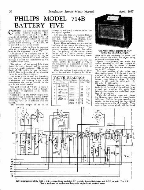
Philips 714 b service manual

This is the 2 pages manual for philips 714 b service manual.
Read or download the pdf for free. If you want to contribute, please mail your pdfs to info@audioservicemanuals.com.

Page: 1 / 2
left right
philips 714 b service manual

Extracted text from philips 714 b service manual (Ocr-read)


Page 2

April, 1937 Broadcaster Service Mans Manual SI

in two brackets on either side of the scale, primary and the primary while trimming !

just above the adjustin screws for the the secondar . h. .
tuning drive Bowden cub es. LP. Glrcu ts.-Switch the receiver to P lllps 714B
Finally, unsolder the s enker connecting long waves, tune the gang condenser to
leads and remove four galls from under maximum capacity and short circuit the on Test
neath the cabinet and the chassis may be oscillator gang.
completely removed. Connect a. modulated oscillator timed to ODEL 714B.-Stsndurd model
it should be noted that this cabinet, is 128 kc. to the grid of V3, via a .032 mid, for battery operation," using
fitted with a removable fibre base plate condenser, and an output meter across the EV Ready Portable 59 H-T-
which is held in place by four small bolts. external speaker terminals. gage? and (ilihauia type ZLG3
Most of the work necessary may be done Use a. .01 mid. shunt condenser and Diisclzitirgigiv Virlguebvafigs 115
without removing the chassis. trim T1 and T2 for maximum output. oscillator haltery snperhbt tgble
. . . Transfer the oscillator lead to the grid of v1, model wfih walnubfinished cabi-
Circuit Ahgnment shunt the secondary of the first 1M. with a
10,000 ohm resistance and trim T3. Remove _ Strai 1H. f 11_
the shunt _ .- gi me u
Notes Shunt the primary with a 10.000 ohm resist vision sen e'Wltll name and wave-
All the trimming wudenm. adjusting ance and a. .1 mid. condenser in series and trim length calibration. Scale not

T4 {or maximum output. Remove the shunt illuminated. Variable selectivit

screws are 39311911 With Wax, Whldl must and repeat the adjustment of T3 Then control ganged with lone. Pusi
he softened With a warm soldering iron. readjust Tl. action muting switch on tuning
Great care should be taken when adjust. LF. Elliot-Transfer the oscillator. still tuned knob. Tone control concentric
mg the trimmem, otherwise the wires 2115:.195'f3,f,fi,3%3fii1fi$mmm d with band width control. Volume
soldered to the heads oi the adjusting Medlum w,,,¢,___pram .015 deg. mph, concentric with wave selection.
screws may he broken. in position and adjust the gang condenser Internal aerial selective by EDS-

In the are; 'below mention is made of against it. If the template is not on hand. then LoiniNG.-L.T., .95 amp.; .T.,
a, 15 de tem late and an an iliar tune the_recelver ~19 206 metres (1,442 km), 7,5 ma.

. 8- P . 3 . Y meet a signal oi this wavelength to the aerial . . . . .

amplifier. The template is for adlustmg and earth terminals via. a dummy rerun and Sens-My and Select-My
the gang condenser to a. required capacity zidiusl. T6. T7 and TE lor maximum output. SHORT WAVES 05:5'52 metres).-
and may be obtained (from Phili 5 service Long William-Tune the receiver to 760 metres Gain and selectiv1ty very good.

- - (395 kc.) or edit the condenser against the Egg handlin no drift. ain well
department. The smpllfier 1 only be template. Inject a signal of 760 metres and mnlhtalned o§ér wavebuni.
needed if the receiver is badly out of adjust T9 for maximum ouhplllr. MEDIUM Wives (1907585 metres).

an and can be the rumo hone side of Image Filteralnject a strong signal of 300 - - - . ~ .
in greliahle radio setg [3 metres (1.000 k0,), tune the receiver carefully to fSenSitwity and selectivity MY?!)
1% . w . the second channel whistle on ivpproximawli' lush Order- In maximum 1008mm
0" LE lmmmg various shunt ' the band Width gives excellent

resistances and. condensers are required fidelity whilst in minimum selec-
tlie procedure being to shunt the secondar}; CONDENSERS tivity Will $9!th adjacent
(7

of one transformer While trimming the . l Purpose. Dim. 013915-, Overlap only presemon
. 7v local stations. Background quiet.
15 Top blind pass coupling .. .00001 Whistles very slight.
RESISTANCES if; 3:33 resuming": -~ l- fig; LONG WAVES (725-2,ooffio).-very
-'-~'-"- W m? 3 '~ high gain selectivitv su cien to
is s.w. d 'l h t.. .. .00002 . . l .
PM]: 19 V1 fillfiiflgxtiflgun .. .. .0001 give Deutschlandsender with sub

stdntiully no interference. Gain
and selectivity Well maintained 1
over wnvebund.

v1 grid .. ..
v1 suppressor grid leak

R

1 20 V1 screen decoupling
2

2 V2 anode decoupling

1

ti

7

B

21 v1 suppressor grill couplln"
22 Osr gang series

V2 anode deconplin 23 L. 090. padding .
v2 grid leak ., 3,. 24 pudding .. Acoustic Output . r .
v2 grid stabiliser . .. 40 25 . W.osc padding Very good for single lngh slope 1
V1 and V3A.V.C. decoupling .5 meg. 26 grid .. pentode, illustrating the value of .
Volume control . . . . .5 meg. 27 A. C. decoupling tone-com ensuting circuits. Sulfi-
0 V4 grid network part .. .2 meg. 28 Ill. filter .. cient v0 me for medium mom i

10 v4 grid network pert .. 1 mg, 20 LF. coupling . . . lliout 0v er} 0 a din

11 v4 grid network part . . .2 meg. 30 L.F. filter .. .. . . .0001 W 3- l

12 A.V.C. diode loud (purl) .. 1 meg. 31 Arvrc. diode coupling .. .0001 _ . ,

13 A.V.C. diode load (part) . . .32 meg. 32 LR coupling . . . . .05 40} metres and trim T10 101' mzmmnm output.

14 V4 unode loud ,. .. 25,000 33 L.F. transformer shunt .001 short Wavee.-Thcre lore no short waive

15 Grid blue network (part) 1 men. 34 V4 anode decoupling adjustments on_this receiver, the circuits being

16 Grid bias network (part) 20,000 35 Tone control .. permanently adlusled by the makers.

i; grlg iii netwmé 21mg; . . 5,000 3? lift. shunt 0009:): ---~

ri as he wor r . . 10,000 3 mega suppressor . .d . .

19 V5 grid stabiliser pi. .. .2 meg. so Muting ,. .. ., .01 . Anfixaci FePIMEWm 9°delsleilio'fcz6

20 V4 nunde decoupling .. 3,000 39 Pentode compensating .. .001 in this Phillips receiver is awm a e ram

3% 33m: antic] ,. H .. .. 50,000 40 Pentode compensating .. .gggoom A. H. Hum, Ltd, of Garratt Lune,

_ an e ecoup rig .. 4,000 41 v3 screen decoupling ,. . . -

23 v3 screen decoupling ,. 20,000 42 v3 anode decoupling .. .005 wandw°h- Lona) SW 1 number

5,472, it is priced at 25. 9d.


[lTuNE
wwc
005
g, Cl6 O
HFGANG
OSCGANG FRd-w (i c2: 05%
. ; COILS
1.1-1? %% C25
22 as R Selle
QPPTRANS V
'
c39::l

Chassis layout of the Philips 7143. The tinted diagram (left) is the top; the right-hand diagram is the underslde.