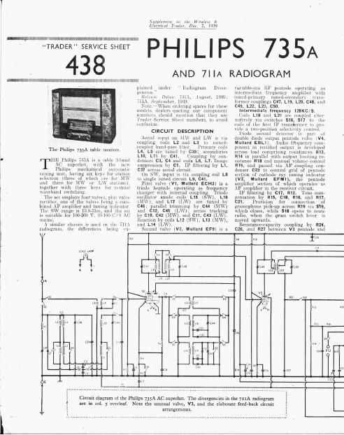
Philips 711 735 a service manual

This is the 4 pages manual for philips 711 735 a service manual.
Read or download the pdf for free. If you want to contribute, please mail your pdfs to info@audioservicemanuals.com.

Page: 1 / 4
left right
philips 711 735 a service manual

Extracted text from philips 711 735 a service manual (Ocr-read)


Page 2

Undenchassis view.
Diagrams of the
wavechange and
radio/gram switch
units are in column
3 overleaf, R22 is
the lever-operated
[one control. R30
consists of two re-
sistors 1n series.

F1xcd 1011 c c0117

pentodosecliun at: V4. _
recuon 1n anode (11110111 by C29. Variable

Jone (:rmtml by 030, C34 11ml R22
between V4 anode and V3 cathode cir-
cuit. Provision for connection of low
1mpcduncc external speaktr ticrnsfi

[maker se10n1l11ry of output transformer
T1.

.\ semnd secondary on T1 provides
1011 ages for negative and positive feed-
bank, which 1111: introduced at xarious
pain 11 one of the, 911111011 51111ch of the
receiver. This secondmy has four out-
lets, one of which IS connected to chassis
so that those either side of it are in
opposite phase to 0m another; that
which is returned to CEO and R19 in-
troduces negative feed- back, while posi-
tive feedback 15 introduced at the

c1 114
ms

Wireless 1!:
Dec. 2, .1939

Supplemen/ m the

1121111111111 Trader,

junction of 818 and R13, R18.

The effect 111' this hitter Voltage be-
comes moie pl'JOIIOUHLCLl 115 lllt' Volume
control is :1111,nnc<1t until at mn\1n111111
position the I]("Qitl\e 11nd positne
voltngm in the (ilcuit nc1111.1l1>1: UilLl]
othe1, and maximum gain is ect1hl15hul
between V3 pcntnrln (G and the output
ci1o11it

The resistances R35, F136, R31, R38
11nd R39 together With condonwisY 63!
C32 and 033 coirect the tiequency 1e-
sponsc of the feed- back Voltages.

Second diode of V4. fed from tapping
on L22 via C19, pmvidts DC potentials
which are developed :1c111~s l11211l Insist
ances R32 and R33 and fed back though
decoupling tircutt: as GB in F( tempt
on SW) and IF inlves, giving AVC.

PHILIPS
735 A

43

J1t21_11 111ltage is obtained t1on1
1111111nt1ul divider ta'mnpiising resistnmm
R3). R31, R32, R33 \Vhich IS (1111111111 tttl
m'mw B3, This DIESOS the diode- 1111111111
111111111 tV,:1nd the 1l111de 1s 15 1111-
Vented ticm 1ectifying 1i1t1 1111nliml Sign 1]
11111] the Signal mounds the John in
mzignit 111111. The pnsitiw potential thus
Implied tc V1 111111 V2 (1)11l111l wills [1
othu liy couespundinuly high til» re-
sis 1111005 in their cathorh circuits.

lli' cmrent is supplied by lull-1111111:
reetttVing 111111.- tV5, Philips A21).
Sn nothing by two electrolytic 111111-
1lr111snrs 028, 035, and resistance, R34.

til} put'mtml for V4 pcntmlu is oh-
tan 11:11 from drop along resistance R40.

COMPONENTS AND VALUES

11 SISTANtES 1,'.,',,',;)
111 v1 111111111119 CG decoupliltu 111mm
112 1 111 potential 1111111101 11 1 , 17 1111
R1 1 \iitancm 1,
5!) 1'1 11ch GB msistances [1 11
1111 \1 054 C1; resistance , 17,0111)
R7 nwillatnr SW traction
damping . l 1.;
1(9 \l 051, anode HT 113111 l "7 1111)
Rl. V CG (Ii-coupling .. 11,,1111011110
R10 \' Sti HT feed reaistancthi 101L110
11H Y1 fixed GB resistance . 120
111: ll- stopper . 2130,1100
RM 1 \J- >ignnl diode load W-I 270.000
1111 1 ~ifitancc5 l 1111,0110
iii; anrts of tone compcnsator ll: :ilitfi
R17 1 "9" 1 -* 1i ' 22,1111.
R Ix V1 1111mc control urn-im- ., , 1111,0110
KIJ M1111ual\,ul control, total 710,000
111111 1 V1: SG HT food poteminl 1 330.1111
R21 1 ilividvr . 470,000
111:: \ 11111111111 tone control .. * 150.1101)
112:1 V11. anode and target HT 1
eetl resistance 1 31111111
I! 24 YE» lit'ntmle anndP load 120,111!)
RL) T. I tame: HT feed 1. 17,0110
1111; wntmle GI} mistauce 1,1100
R27 CG rusistance 4711,0110
1119 CG choupling 1110, 0110
R2:- \6 111-111 stopper .1,0(111
11141 of HT potentiiil 11411111111111
ml Mei-rm ACdelay ., (1.0110000
R11: > V0 diode load 111-11 410 1100
111:; 1 \istauces .. 4711,1100
, RM \1 11:, (and V4 sinl'l'l
fleet] .. 1,5111
1 R15
1111; i i, 1:101)
R17 - hedrback feed rFsistimces - 4, 7110
R 111 l 101x111
v.11- . , 1121101111
1 11111 1 111mm GB n-niLaiit-e . 11111

1
17. ____fi* fi o
T111101} at 50,000 (l tmm low potential (Lil!
1 11111111 1111 111 two 4 700, 1100 O resistances 11111111111