Philips 680 a service manual

This is the 3 pages manual for philips 680 a service manual.
Read or download the pdf for free. If you want to contribute, please mail your pdfs to info@audioservicemanuals.com.

Page: 1 / 3
left right
philips 680 a service manual

Extracted text from philips 680 a service manual (Ocr-read)


Page 1

Service Mains Manual

mg

Radio Market

lulv, 1 940

PHILIPS 680A

Three-valve, plus rectifier, three
waveband, push-button superhet for
A.C'. supplies.

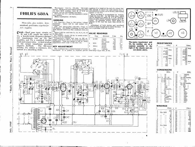
Circuit-Band pass input circuits on

. and L.W. couple the serial to
Vl, a hexode-triode frequency-changer.
I.F. transformers link up V2, the
amplifier, and V3, 9. combined double-
diode and output valve. A third winding
on the output transformer provides
negative feedback. The full-wave
rectifier, V4, utilises a. resistance, R],
instead of a smoothing choke.

Wayebands: 13.8751, 175-585, 708-2000
metres, Mechanical push-button tuning provides
for three BLVV. stations, three M. or L.W'. as
desired. and for wavechange switching.

Provision for RU. and iow-impedance exten-
sion speaker.

Mains consumption : 50 watts.

GANGING

LF. CIRCUXlSl-Tune to 180 metres, volume
maximum. Inject 123 kc. and adjust Ir.
trimmers.

RI. AND Oscl'LLATox Cmcvlr -Tune to
180 metres. Fit Philips' trimming g and turn
pluck manual control so that condenser rests on
l g.

Inject 1,600 kc. and trim CE. 18, 10, (l, 10, 18
in that order.

LF. Fln'rim.~Apply 128 kc. to aerial socket.
Adjust 013 for minimum.

GALXBRATION.*Inject anrl tune to 530 m.
Adjust pointer to 530 m. by screw provided in
mechanism. Tune and adjust to 210 ni., using
adjustment screw near to the first one.

KEY ADJUSTMENT

The condenser has a lateral Instead of rotary
movement. It is pushed to required pro-set

positions by a crank at the end of a rotary bar.
The amount of travel for each station key is
determined by a screW. set In the key, and hen ring
against a stop but.

Wave switching is accomplished by rockers,
which the keys tilt. 0n the three keys, which
can be adjusted to either M. or L.W. stations,
there are arms which normally operate the L.W.
rocker. By releasing screws, these arms are
allowed to fall and the keys then switch to
M.W.

Adjustment of both station and wavebhnd
screws is made through holes below the keys. A
tool is provided with the receiver.

VALVE READINGS

1 Type Electrode Volts 11111.
l-JCH3 Anode 5 1..
Screen 70 iii
080. anode 140 4 .3
2 EFQ Anode 250 5
Screen '90 1.5
3 EBLI Anode 21.70 32
Screen 240 5.2
4 AZ llmhode 300

1
Dial lump-Type 8091, D700.

0
c l
.

C18

C

@o.

C
IO
0
o
o

""1

:ogcl OIFKP)
1----

l

I BP

133,321-1

L34© 3m},

Em ®

The mains transformer and

V4, the rectifier, are on a.

separate assembly to the

right or the chassis and are
not shown above.

RESISTANCES

R Ohmr.
l . . 1,800
3 .1 meg
1 47,000
5 . 030
6 . . 27,000
7 _ .1 meg
8 . 17,000
9 .65 meg
9.1 . . .05 ,,
10 1.5 ,,
11 1 ,,
12 150
13 390
CONDENSERS
o Mfds. 0 Mm.
1 . . 50 21 . . 000394
2 . . 15 22 .017
01' 1+2 32+32 23 70-100mmde
:5 11400 nnnrils. 21 7071 00 ,,
4 11-190 ,, 25 . . .017
5 11400 20 . . .047
(s . . 20 ,. 27 70100 mmfds.
7 . 10 ,, 28 70-100 ,.
S . . .012 29 . . 8.2 ,,
U . . .039 31] , . 56 ,,
10 . , 20 mmfils. 31 . . .0033
ll . . 2.2 ,, :52 . 25
12 :59 ,, 33 . . .001
1: 10-100 ,, 3-1 .. .0047
11 .017 35 . . .033
if. . . 17 mmids. 30 . .0050
10 . . .00047 :17 .. .027
is . , 20 iumfds. :10 .. .0001
19 . . ,, 42 . . .0047
20 . . .00145 ~13 . . .047
WIND! NGS
L Ohms. L (Mn 1.
2 . . . . ' 00 19 . . . . 9.5
3 less than .5 20 1 . . . 115
1 ,, .5 21 . . . . 115
IS . . . . 26 22 . 1 . . 115
7 . . . . 90 23 . . . 90
S . . . . 4.5 24 . . . . 35
9 . . . 48 26 . . . . 709
10 . . . 4.4 26 . . . . l
11 . . . . 45 27 . . . . 2.5
12 . . . . 2 29 . . . . 110
1:; less than .5 30 .. .. .7
14 ,_ .5 31 . . . . .7
15 . . . 1 32 . . . . 181)
16 . . . . 8 33 . . . . 150
17 . . . . 2.6 34 . . . . 800
- - 18 . . . . 32

Page 2

PHILIPS 680A
MULLARD MASEM

T/lrcv-mlvr'. plm I(('!l/it'l. rllrw lml-t'bulll!
All/Itl'hfl/ for operation ml 4C mail of 100»
250 rolls. 0»100 (I/43 Fiml/ nil/l [mt/r
ImlIu/Ix fiu- \llllmm um! llam-llangillg aml wit/l
rim/am fur pick-up mwl z'wmlximl \{U'Ilktr
Afar/toyed by Phillips Lam/Lt. Llrl.. um/
Mal/(ml Wirl'lpn Slll'ltt (0.. erl.. (all/117]
Hal/11'. Sim/Mb!!!) Artmu'. Lulu/rm, WC;

()Nmedium and lung wllves u bandpass circuit

15 employed in which the ucritll signals are
coupled by Lb. L7 and (:7 to the prlmary coils
L8 (MW) and L9 (LW). These are tuned by VCl
section of the ganged condenser.

Secondaries of the bandpass unit are L10, L11
tuned by \C2. and the signals are for! direct to the
grid of the frequency changer V1.

Bandpass coupling is effected by L30, L31, C8
and C9, and an intermediate-frequency rejeetor
circuit comprises L29 and C13.

0n short waves the aerial input is fed to the
iogpling coil L1: and thence to the tuning coil

V1 is cathode biased by R21 decoupled by C14
and has automatic volume control applied to the
grid circuit on MW and LW only. R3 and C43
are the AVC decoupling components.

The oscillator triode section of VI employs grid

A 920

$2

(a.
24 ' I,

31

E C9 C45

Yhe HAS" 3! a "short superhet wish band-pin input.
on tho weak-r transformer.

FEBRUARY 1946

leak R4 and condenser C15 with feed-back coils
L15, L17. L19. The tuned anode coils L14, L16
and L18 are fed from the anode circuit via C16
and are tuned by VC3.

1F signals are transferred by transformer L20
and LZl to the grid of the pentode V2 which is
AVC controlled. Standing bias is provided by
the cathode resistance R5. decoupled by C26.

A second IF transformer, L22, L23 passes the
signal on to the signal diodc of the double diode
output pentode V3. 1F filtering is by R8 and C30.
and the volume control R9 is the load resistance.

Audio frequency signals are fed via C31 to the
grid of the pentude section of V3. HF filtering is
effected bv (739.

The AVC diode of V3 is fed from the anode of
V2 lla C29, the load resistances belng R14 and
R23. Full control Volts are applied to V1, and
the smaller voltage to V2 from the junction of R14
and R23. ,

Delay voltage is obtained from the muimum
bias across the cathode resistances R12. R13.
while the junction of these two resistances provides
bias for the pentode section of V3.

VI

4 L20 L21

R4 915 T

R5
C25 C

Pickup sockets are provided across the top end
of the volume control R9 and chassis.

The output transformer L25, L26 couples V3
to the permanent-magnet moving-coil loudspeaker
in which L27 is the speech coil. Sockets are pro
vided for an extra low-impedance speaker having
a DC resistance of approximately 25 ohms.

A tertiary winding on the output transformer.
comprising L32 and L33, provides positive and

Continued overleaf

VALVE READINGS

V Tl'llt Elt't Irmlt as
l [(le _ Amide T2
Obtaflnttdc 4 3
Screen 1.3
Culhudc .
2 Fl") Anode
Screen
('Jlllttdc
.1 LBLl Anttdt
Screen ,
('nllout .
4 All lrilumenl DC
V4
A A
H H
A Z I

C 29
L22 L25
7
V5

R1 ' z
32

The output mu incarnate. negative land-back from n turtiary windinl
Tn. push-button tuning i! purely mttnanlcul.

ms; unions 30M»
ugnuu all mus my: mama Hut was mt


won
mun

mum

min-it
um scam

"mm mum;-

This cabinet houses the Mulhrd verlion.
Theru are three buttons (or wivechanfl g.
three for medium wave preselected stati .
and three which can be set [or either medium
or long-wave programmes. The manlca|
tuning knob is depressed lor operation. A
lever type 0' tone control is titted.

RESISTORS
0mm . R 011m

I . 1,000 14 560,000
3 100.000 13 1.500
4 47,000 16 50.000
5 330 17 12.000
6 27,000 lit 10,000
7 100.000 19 820,000
2% 47.000 . zu . . . 47,000
9 650.000 21 . . 330
9.: 50.000 22 13,000
10 . 1.5 meg. 23 560,000
11 I meg. 24 l x meg,
12 150 27 15
13 390

CONDENSERS
t' Mm ( M/dy

. 1
2 15 25 .047
7 , 00001 29 . 8.2 mmfdl.
s 012 30 56 minus.
9 .039 31 .0033

11 2.2 mmfds. 32 ,. ,. 25

12 .. . . 39 mmfds. 33 .. .. .001

14 . . . . .047 34 . . . . .0047

15 .. ,, 47 mmrds. 35 .. .. .033

16 . . . V .00047 36 . . . .0056

19 .. ,. 33 mmrds. 37 .027

20 . , .. .00145 39 .. , . .OOOI

21 . . . . 394 mmtds. 42 ,. .. .047

22 .047 43 .047