Philips 660 a service manual

This is the 4 pages manual for philips 660 a service manual.
Read or download the pdf for free. If you want to contribute, please mail your pdfs to info@audioservicemanuals.com.

Page: 1 / 4
left right
philips 660 a service manual

Extracted text from philips 660 a service manual (Ocr-read)


Page 1

22

Broadcaster Service Mans Manual

PHILIPS 660A PUSH-
BUTTON FIVE

ROUTE-The serial input circuits
consist of H.F. transformers on all
wavehands, the secondaries being tuned
and the signals fed to the grid of V1, 3
hexode valve operating as an H.F. amplifier.
A series grid condenser, 018, enables the
A.V.C. potentials to be applied direct to
the rid.

H. . intervalve transformers rovide
the coupling to the frequency c nger,
V2, with extra coupling in the form of
C43 on the medium waveband. Here
again a series grid condenser is used.
A.V.C. potentials are not a plied on the
short waveband. The cscifiator section
follows standard practice, the grid coils
being tuned.

An I.F. transformer of the driftless,
non-trimmer ty is tuned to 470 kc. couples
the frequency c anger to the H.F. pentode
I.F. amplifier, V5. It will be seen that
when the receiver is acting as a graine-
phone reproducer, V3 is connected to
operate as e triode L.F. amplifier.

VALVE READINGS

No signal. Volume maximum. liLW. band
200 Volt AC. mains.
V. TYPE. Electrode. Volts. Ma.
Mullardl
1 EFS . . . Anode . . 205 4.3
Screen . . 190 .i
2, EK2 . . . Anode . . 190 2.2
Semen . . 180 3.5
Oscmnode 00 1.3
3 FUN . . . . Anode . . 200 6.5
Screen . . 90 2
EBLI . . . . Anode . . 235 34
Screen .. 260 5.6
Philips All . . Heater . . 290 --

Another I.F. transformer couples V3
to the demodulating diode of V4, 3,
double-diode output pentode. The
primary and secondary windings are both
tapped down. The connection to the
demodulating diode load is effected via
an H.F. filter, and the rectified potentials

- fed to the grid of the pentode section of

V4 via. a. tonercompensated volume con-
trol. coupling condensersnd grid stopper
resistance.

A pentode compensator condenser is

included to conform with standard prac-
tice, while a tone-control circuit, C42,
R52 and R55, is included.

The other diode of V4 provides a DC.
potential that operates the A.V.C. net-
work controlling V1, V2 and V5. The

January, 1939

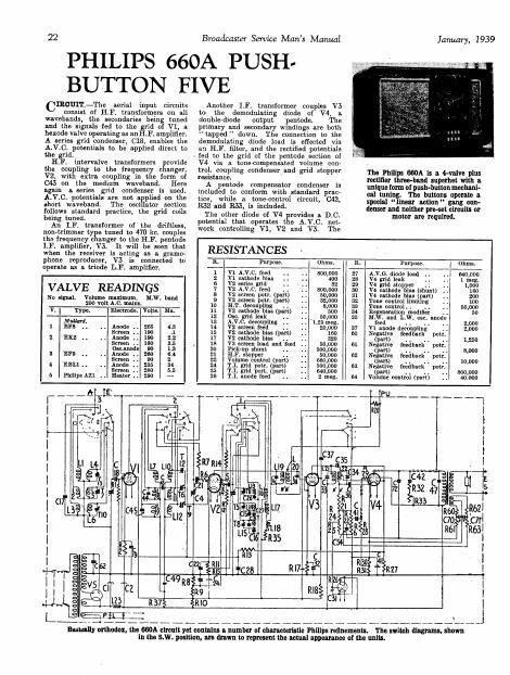
The Philips 800A is a 4-valve plus

rectifier three-band superhet with a

unique ionn o1 push-button mechani-

cal tuning. The buttons operate a

special iineor notion gang eon-

dsnser and neither pro-set circuits or
motor are required.

R. l Purpose. ' Ohms. k. Purpose. I Ohms
1 'V1 A.V.C. feed . . -00,000 27 A.V.0. diode load . . . .l 040,000
2 V1 cathode bins . . 400 28 V4 grid leak . . . l meg
6 v2 series grid .. 32 29 v4 grid stopper .; 1,000
7 V2 A.V.C. feed . . 800,000 30 V4 cathode bins (shunt) 100
8 V2 screen potr. {part} 50,000 81 V4 enthode hiss (part) 200
9 V2 screen potr. part) 32,000 32 Tons control limiting 100

10 ILT. decoupling . . 8,000 33 Tons control 4 . . . 50,000
11 V2 cathode bias (putt) 500 84 Regeneration modifier . , 50

12 Osc. and leak . . 50,000 35 M.W. and L.W. 05c. anode

13 A.V.C. decoupling . . 1.26 mag feed . . . . . . 2.000
1- V2 screen feed . . 20,000 37 VI anode decoupling . 2,000
15 V2 cathode bins (part) 160 00 Negative feedback pot!

17 V2 cathode bin . . . . 320 (part) . l . . . 1,250
18 V3 screen load and feed . . 50,000 01 Negative feedback potr.

20 Pick-up shunt . . . . 00,000 (pm . . . . 4 3,000
21 Hr. stopper .. 50,000 62 Negative feedback potr.

22 Volume control (part) (560,000 (part) . . . . . . 10,000
24 T1. grid putt, (part) 500,000 63 Negative feedback putt.

25 TJ. grid port. (pm) ,000 put . . . . . . 800,000
26 T.I. anode feed . . 2 meg. 64 Volume control (part) . . 40.000

l
|
|
|
l
l
I
l
l
I
l
l
«l-oT
ll} v5C

>i-4Lo 3 3
L 5933::

NS

l0

\ J

~-\._4________._.___#_ ____A______ ____._.___.__._._-.__

Blnfllly orthodox, the 860A circuit yet contains a number or characteristic Philips refinements. The switch diagram. shown
in the s.w. position, are drawn to represent the actual appearance oi the unit.

Page 2

January, 1939

Potentials operating the pentode section
of V4 also operate the visual tuning
indicator.

Mains equipment consists of a mains
transformer, a full-wave rectifying valve
V5, electrolytic smoothing condensers
and separate smoothing choke.

Chassis removal.-The cabinet has a
false bottom secured by six screws, re
moval of which enables access to the
underside of the chassis. The chassis
should not be removed if avoidable.
If it is necessary to remove the chassis,
the following procedure should be
followed :-

Remove the two grub-screw fixed
control knobs from the front of the
cabinet and also the back, which is
secured by sliding clips. Then remove
the four recessed chassis-seeming bolts

tuning indicator and bolder.

Broadcaster Service Mans Manual

and washers from the base of the cabinet,
taking care that the chassis does not fall.

Loosen the grub-screws securing the
tone and volume knobs to the extension
shafts inside the cabinet, then unhook
the cable from the tuning pointer drum,
and, still holding the drum, unscrew the
fixing screw securing the drum and allow
the spring tension on the drum to slowly
adjust itself. Then unhook the cable
from the wavelength indicator, unscrew
the brass cable, insert rod, and remove.
Unsolder the two speaker leads and the
earthing lead to the plate at the rear of
the chassis.

Unclip the dial lights and holders from
thelr mountings and remove the visual
The chassis
may then be removed from the cabinet
free of all leads.

(Continued on page 24}

C. Purpose. Mfds v0 INDINGS (D.C. RESSTANCBS)

1 1131. smoothing . . . . 28 . L. Ohms. Range. Where measured.

2 111'. smoothhu . . i . 32

17 L.W. aerial shunt .. . .00008 1 2.4 S.W. Aerial socket and
18 V1 grid isolating . . .0001 chassis.

19 V1 cathode bins shunt .1 2 25.1 M.W. Aerial socket and
21 V2 y'id isolating . . .0001 chassis.

22 V2 cathode bias shunt . .1 3 105 L.W. Aerial socket and
23 V2 screen decoupling .. .1 chassis.

24 HI. decoupling . . . . 32 4 .1 .W. 01 and chassis.

25 Use. Did . . . . . . 00005 5 4.9 TLW. 018 and chassis.
26 5.W. Dec. fixed padder .00475 6 45 L.W. 018 and chassis.
27 M.W. osc. fixed pndder .0004 7 3 S.W Anode V1 and C49
28 . C. decoupling . . . . .1 8 270 M. . Anode V1 and C49
£1) T 1 prim. fixed trimmer .000091 9 486 L. . Anode V1 and 049
': 1 , 1 sec. fixed trimmer .000007 10 Very SW. C21 and clwssls.

I . grid decoupling. . . . .05 low

1. cathode bias shunt . . .05 11 419 M.W. C21 and chassis.

.. ) T.2 prim. fixed trimmer 000103 12 441 L.W. (121 and chassis.

l T.2 sec. fixed trimmer 000103 13 Very S.W. C25 and C26

5 diode decoupling low.

.34} . Tess . . 14 8.8 ILW. C25 and C27.
31 screen coupling . . . 15 . 18 L.W. C25 and M.

l 41 . coupling. . . . 16 1.2 sw. Osc. anode and 0.24
4}. Toné control. . . . . 17 3 LLW. One. anode and R35
43 M.W. 11F. coupling . . .000002 15 4.3 L.W. (lemonade and R35
44 M.W. HT. primary tune . . .00005 19 9.3 - Anode V2 and C24.
45 L.W. H.F. primary tune . . .0002 20 8 - Top mid V3 and
43 V4 cathode bias shunt . . 25 320.

47 Pontode compensator . . 2 21 fpart) 4.4 - Anode V3 and CZ.
48 L.W. osc. fixed trimmer .. 00004 22 part) 3 - E21 and demodu-
49 V1 anode decoupling . . .05 ' latlng diode V4.
60 , Tone compensator . . . . .05 23 400 - Tags.

62 Rectifier hy- s3 . . ' . . .02 QT. prim. 630 - Tags.

70 Negative fee hack injection .064 BLT. prim. 33 Mains plug pins.
71 Neflltlva reedbsck injection .002 (200 v.).

72 Food back coupling . . .000125 Total HE. 450 ~- Anode pins V5.

VOLUME

ON/OFF "2 m)
Ulekéz

snow 0


LS

'U

l .
62AM RADlO SWITCH

I-l.F.

AERIAL.

U

Above, a layout diagram idenlilying all the components mounted inside the

Philips chassis.

011 the light is a diagram or the pointer drum (see notes on

chassis removal and replacement).

Philips 660A
on. Test

ODEL 660-A.-For AG. opera-
tion, 100-260 volts, 50400
cycles. Price 13} 3113.
Dascarmon. - Four-valve, plus
rectifier, push~button superbet
covering three wavebands.
Framers. ~ Eight push-buttons
give choice of any combination of
medium and long wave stations.
Mechanical system using linear
action" gang condenser. Full-
vision circular scale calibrated in
metres and station names. Nearly
360 degrees of inter rotation.
Speaker at side 0 chassis. Con-
trols for tone, combined volume
and master switch, tuning and
wave selection. Wavechange
switch operates indicator on scale.
Visual tuning indicator. Sockets
for pick-u with gram/radio
switch. Soc ets {or speaker.
Lommo.-60 watts.

Sensitivity and Selectivity

Snonr WAVES (16.7-51 metres).-
Excellent gain and selectivit .
Very easy handl' . No noticeab e
drift and particu arly well main-
tained gain.

MEDIUM WAVES (198-585 metres).
kExcellent gain and selectivity.
with local station spread on
adjacent channels only. Clean
background and. well maintained
sensitivity.

LONG WAVES (7082.000 metres).-
Similar performance to medium
wave band, with very little inter-
ference on Deutschlandscnder.

Press-button Notes .
The press-button adjustment is
easy. The setting was accurate
when received and did not shift
during our tests.

Acoustic Output ,

Ample volume for an ordinary
room, with a pleasing characteris~
.tic, a reasonable amount of is per
note response and crisp, 0 can
attackand a not too vigorous tone
control. Medium registers are free
from resonance and the low note
radiation is very good.

Replacement Condensers
EXACT replacement condensers avail-

able from A. H. Hunt, Ltd., Garratt
Lane, Wandsworth, London, S.W.18, are:
for either C1 or 024, unit 4235, price 73.;
for 02, 4265, 73.; and for C46, 2918,
La. 9d.

DRIVING ,
DRUM G


power .
screw SPINDLE E