Philips 599 a

This is the 4 pages manual for philips 599 a.
Read or download the pdf for free. If you want to contribute, please mail your pdfs to info@audioservicemanuals.com.

Page: 1 / 4
left right
philips 599 a

Extracted text from philips 599 a (Ocr-read)


Page 1

IIIIlIllIIIIIIlIIIIIIIIl||||II|I||IIII||lllltl||lllltl||IIllllIlllllIIIIIIIIIIIllIIIIIIIIIIIIIIIIIIIlllIIIIIIIIIIIIIIIIIIIIIIIIIIIIIIIIIIIIIIIIII lllllltilllllllll

"TRADER SERVICE SHEET

464

IIIIIIIIIIIIIIIIIIIIIIIIIIIIl|I|IIIIIIIIIIIIIlilllIII|IIIII|IIIII|IllII|IIIIIIIIIIIIIIIIIIIIIIIIIIIIIIIIIIIIIIIIIIIIIIIIIIIIlllIlIIIIIIIIIIIIIIIIIIIIIIIIIIIIIIIIIH

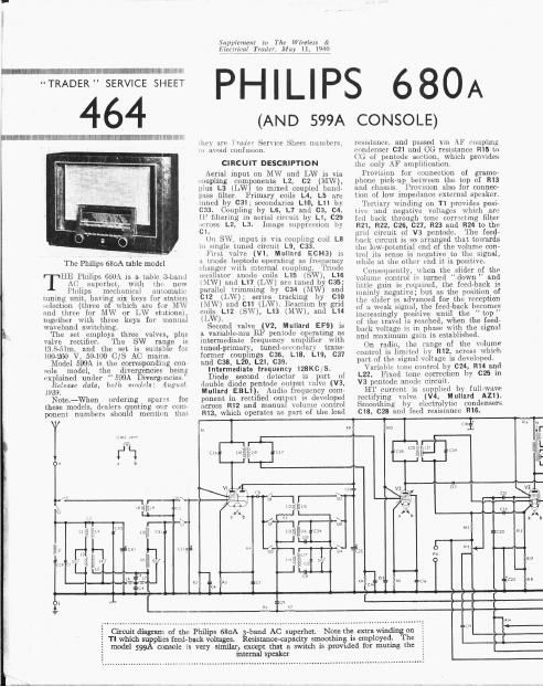
The Philips 680A tsble model

HE Philips 680A is a. tttblc Et-bantl

I A0 superhet, With the new

_ Philips ineehaiiieul llLlIUlIlaLlc
tuning unit, havtng six keys for station
MiCClZlOD (three of which are fur MW
and three for MW or LW st ttions).
together with three keys for manual
wavoband sWitching.

The set employs three. valves, plus
valve rectifier. The ran e is
I3.8-5lm, and the set is suitabe fm
100-960 V, 507100 C/S AC mains.

Model 599A is the corresponding con
sole model, the divergenoies being
explained under 599A Divergencies.

Release data, both models: August
1939.
Note-When ordering spares {0)

these models, dealers quoting our mm-
ponent numbers should mcntitn that

m. mm

{3

5 TI which supplies feed- back voltages.

Supp/email! in The Wirzlexx or
1940

Idlerrtiral Trader, May 11,

(AN D 599A CONSOLE)

itr) are Inutvr Serut'e Sheet numbers.
n avoid confusion.

CIRCUIT DESCRIPTION

Aerial input on MW and LW is via.
t'oupling components L2, C2 (MW),
plus L3 tLW) to mixed coupled bond-
[Liss filter. Primary coils L4, L5 are
tuned by C31; secondaries L10, L11 by
033. Coupling by L6, L7 and 03, c4.
II" filtering in aerial t'irrmt by L1, C29
gross L2, L3. Image suppression by

1.

()n SW, input is via Coupling coil L8
In single tuned circuit L9. 033.

It'ttst valve (V1, Mullard ECHS) is
it triodo lieptode operating as frequency
manger with internal coupling. 'lriotlt:
():CillaL01 anode coils L15 (SW), LIE
t,\l.W) allLI.Ll7(L\N) are tuned b C35;
parallel trimming by 034 (MWlY and
012 (ltW); series tracking by CID
(MW) and C11 [LW). Reaction b grid
coils L12 (SWI, L13 (MW), an L14
(IAN).

Second valve (V2, Mullard EFB) is
a variableunu RF pentode operating as
intermediate frequency amplifier with
tuned-primary, tunedrsomndury trans,
former couplings 036, L18. L19, 037
and 033. L20, L21, C39.

Intermediate frequency 128KC/s.

Diode second detector is part: of
rlouble diode pentotle out-put Valve (V3,
Mullard EBLI). Audio frequency comr
[1011th in rectified output. is developed
across R12 and manual volume control
H13, which operates as part of the lottd

Circuit diagram of ch Philips 680A -band AC superhet. Note the extra winding on
' csistance-capaciry smoothing is employed. The
model 599A console is very similar, except that a switch is provided for among the

internal speaker

resistance, and passed via AF mupling
(condenser C21 and CG resistance R15 to
(IQ of pcntode section, which provides
the only AF amplification.

Prov ion for mnncction of gramor
phone pick-up between the top of R13
and chassis. Provtsiun also {or connec-
tion of low impedance external speaker.

Tortiary Winding on T1 provides posir
tivo and negative voltages which our
fed back through tone correcting filter
R21, R22, C26, C21, R23 and R24 to the
grill circuit. of V3 pentodc. The feed-
back circuit is so arranged that towards
the low-potential end of the Volume con
trol its sense is negative to the signal,
while at the other end it is positive.

Consequently, when the slider of the
Volume control is turned down and
little gain is equii'etl, the feed-back is
mainly negt ~vo; but as the position_of
the slider is advanced for the reception
of it weak signal, the feed-back becomes
increasingly positive until the top"
of the travel is reached, when the feed-
buck voltage is in phase with the signal
and maximum gain is established.

0n radio, the range of the volume
control is limited by R12, across which
part of the signal voltage is developed.

Variable tone control by 024, R14 and
L22. Fivcd tone correction Ivy 025 in
V3 pentode {mode Cirouit.

HT current is supplied by full-wave
rectifying valve (V4, Nlullard A21).
Smoothing by electrolytic condensers
018, (223 and feed resistance R16.

m

RIC

new in
Us

Page 2

Plan view of the
. chassis. Note the
: various air-dielec-
: tric trimmers,
: Some of them
have small parallel
fixed condensers
: attached to them
: beneath the
chassis. Con-
densers cw, C28
may be in a single
unit in some
models

L " DISMANTLING THE SET

Removing Chassis.~l{ci1iove the six
svrcns (two 111 ouch top corner and
one 1n each bottom corner, with
Wnohcrs) holding the brackets on the
cabinvt surround to the front mould-
mu;

i'omovo the two long transit bolts (with
washers and wooden blocks). if still
in position, holding the ends (ii the
rear member 01' lbs chassis to thc
bottom (it the cabinct;

1'11m0v11 t.ln1 two screws (with washers)
holding Lilu ilexible incoming clamp,
in the centre of the roar chassis meni-
lwr. 11o 1111c bottom of tho cabinet:

remove the two small dinmetor mains
input bracket mounting screws (with
washers) ;

removr the four screws (with washers)
holding the mains transformer to the
bottom of the cabinet
lhc front moulding can now be Willie
drawn, with the complete assemblv

:24

121
C27

klt

m The Wireleir &
May 11, 1940

.iupplmmi
Eimnmi may,

Removing Speaker. ~Unsolder from thc
Gonna 1mg strip on the snooker the
two lcziLls cunucctlng ii to Chas s;

rcmow the four hoxligon nuts (with
washers) and one choose-head screw
(at mp With flsliFll holding the
sliczikei to the i1unt inouidina

ll hm; mplaaina. the speaker connecting
strip should bc (in tho rlght.

Uoiincct the lead from the upper left-
hiind in" on be rear of ll1111 output
irlilleOI'DJCI' to the two upper tags on
the connecting strip;

l'nmlekb the remaining lead (from the
lou11i'lefth1111d tag on the rear of the
4111mm transformer) to the bottom tag
on llm connecting shin.

COMPONENTS AND VALUES

1 . V _ 1 Valm
( UhDEthKS (91,)
(11 imagl' [Ejector 0 (VX1189
('2 Aerial " ton coupling 11-00001
03 1 Band pas'lxouyllnz 0-012
{'14 i nondnnacrs 1 0039
C5 Aerial circuit SW trimmer 010000022
06 V1 501 lit'coupllm: . 01017
C7 Vi cathode by-pass .1 0-0
as V1 use. (10 Condcnscr 01000047
Cl? AVG line dI-I'DllnlinL' 01047
010 Osc. circuit, )IV trucker . 0-00145
011 030. circuit. LW trar-ker 01000694
012 One. circuit. LW trimmer 01000033
018 V1 use. anode coupling 000047
CH V2 CG decoupling 0-047
015 V2 113 dr'lollpling n 047
C16 V2 cathode liy-Dass... . 01047
017 Coupling in V3 AVC (llo 010000052
013* HT smoothing condenser 1 . 20
CW Put of ftEKl- back Coupli g 01027
cm 111' 11y pm .. 0101111
C21 AF coupling to V3 '
usntode 0-0033
022 . IF by mass . 1 o-rxmsa
(CZP V3 cathode h ans. 25-0
(:24 Part of 17811-11718 tone i
. control 0-0047 1
025 Fixed [one cox-rector 0-001
(126 1 FeedAhaA'k tone. { (11033 i
(127 i Corrector condensers 0'00?!
(728 HT smoothing condemn... 3210
(320: Aerial IF filter tuning 0-0001
can: Band-pass prl. MW
trimmer 0'00002
ail gang-pass pri. tuning 11-00049
on mass soc. MW
trimmer 0100002
0331 Aerial SW and band- mass
secondary tu -0*lel4il
0341 05c. circuit MW trimmer 0'00007
E735 Oscillator circuit tuning
1 036 1st ii" trans. mi. tuniml
1 037 lit 1}" trans. am tuning -
033 2nd Ii" trans. prl. tuning 0'0001
C391 2nd IF tram. sec. tuning 0-0001
' Electrolytic i Vnriablz. I "Pro-Ml].

i

[ll

2
[(3
114
[(5
R6
117
R8
R0
R10
K11
R11:
[(112

K11"
1111~
Inn
Elm

R91

L, .__i ,

464 63323th

RESISTANCES

1! Vi ht: HT fccd potrniidl
i divider .
\ 1 fixed GB sistance
Vl use. CG rcslstancn
Osc. SW reaction damping
1 1V Cline decoupling rrsist-
1' once: .
V1 osc. anode HT {and
V 2 CG decoupling
V2 36 HT feed .
V2 fixed GB .i
Volume control Imitu
Manual volume control;
signal diode ioarl
l Variable tone control
l V3 pentndc CG resistanna...
H E feed resistance
V3 [lentodn GB 4\l1'tir1lriy
i 1 resistances ,1
1 V AW (iimlt load rosin-
i tunces .

[Fred-back trcd resistances

. 1 1.100000


11113
l (ohms)

{ um. l
:nm)

.Cifl

17,0111)

1:.

104) 11011

1 150
390
i 560,000

1311111111 at 50,000 0 irom [OW niitcntml (1nd

OTHER COMPONENTS
Aerial IF filter roll
Aerial MW coupling mil .
Acrini LW coupling coil .
1 } 31111111135125 primary foils -
I 1 11111111119511 coupling coils
L8 Aerial SW coupling mil
1.9 Aerial SW tuning coil
iii 1 Band-puss secondary coils ;
[112 Oscillator 5W reaction coil
1,111 Oscillator MW reaction coil
l114 Oscillator LW reucuuu coil
11171 05:21 circuit: SW tuning coil
1.16 05c. circuit. MW tuning coil
L17 Osc. circuit LW 1)tiinlng coil
ms 1 1 1- . ..
Llii Isl: IF trans 1 if?
121 1 1 l r
1121 12nd 11 "1 1 51311., total
L22 Tone control choke
LZIi Speaker speech gall
1r1 Output 1.1m. l Sec.
1 Tart
(r111. total.
11., 3131115. Hea'ter sec.
" trans. in? heat ace.
ET seci, total .
Sl-SN anabund switche
1915. SM Mains switches, gungfld Ria

V 11 nos
Vfllillll!)

5
1D

7
17
0
10
4'4
51)
110
215
5
lo
'0
D

0

1w::&.

e:
m
12
s

0
gm.--
51:11:36.me e
a

ii§¢9$§e§s
cnwaaocu