Philips 588 a service manual

This is the 3 pages manual for philips 588 a service manual.
Read or download the pdf for free. If you want to contribute, please mail your pdfs to info@audioservicemanuals.com.

Page: 1 / 3
left right
philips 588 a service manual

Extracted text from philips 588 a service manual (Ocr-read)


Page 1

October 13, 1934

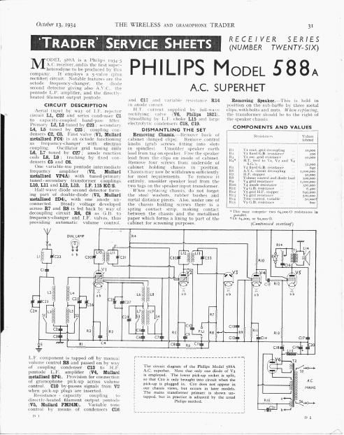
0DEL 588A is a Philips 103.375
M;\.L.rvceiver,nnd is the lint supp ._

heterudviie to be produced by (II 5
company It employs a jazilie lplis
chtifitr) (intiiit Brifzihle feature» lire [lie
mtnrle frequent» hunger [in «Imde
second detector ing 3150 A. I l the
pcntodi: l. I7 amplifier and the iIIKKiI \.
heated filament output pentude

CIRCUIT DESCRIPTION

ACIIGI input by 'in cl 1 I ran-(:1: r
tircnit L1, C22 and sei us coiidwnser C],
to czipiiliti' coupled bandrliil" ilIUl

Primary L2, L3 tuned by 023 ; ruinlnrl
L4, L5 unmi b) 025 coupling mp7
dcn CZ, C3. First Valve (V1. Mullard
metallised F041 is :m mtcirie functioning
as iItKlllt'nty iaiiuer with electmd
coupling. 0 illzitor grid tuning coils
L6. L7 tiincd b) G27: anode martin]
CSOII L8 L9; tracking by fixed kUlIr
densers C5 and 06.

One \ariubleinui pcntodc intcnncdiuts-
frequency amplifier (V2, Mallard
metallised VP4A) with tuned primnri
tuned-secondary transformer coupling
L10, L11 and L12, L13. I. F. 115 KC 8.

Ilallrwave diode second detector fonnr

iug part of double-diode (V3, Mallard
metallised 204), with one anode uni

(onnerted Steadi \oltage divelvped
across R7 and R8 is fed back bx Win at
decoupling circuit Be, as as GB t7

TRADERF; SERVICE; . SHEETS -*

THE WIRELESS AND GRAMOPHONE TRADER 31

RECEIVER SERIES
(NUMBER TWENTY-SIX)

PHILIPS MODEL 588A

A.C. SU PERH ET

.md Cl? JIIKI
in anode \ Iriliil.
ILT \llrI'tlli

\Llllallll reshtiinle R14
nippinu h} lirlirunn-
i'EtliItinj: \ulu- 1V6. Philips 182111
Smoothing by Li choke L15 and [arm
elcctmliiir lnmltIHCh 018, 019.
DISMANTLING THE SET
Removing Chassis. dtemrne hark m
iahiml ihiiiued LIipS) Runuw Lolitrul
knoll: lurid» screws muting intn slot.»
in spindle-v] Unsoldei speaker carth
lead from tag on ~11enl lead [mm the tlips on inside 01 Cabinet
Remove tour screws 1min underside 0i
labinet holding chassis in position
(Iiassis HXEIV now be withdrawn sullicientl}
lor most requirements. To rcmnvc it
entirely. iinsolder speaker lend 1mm the
two tags on tliu speaker 111put transformer.
Ilhm i'elearmg chassis. do not forget
the Steel washers ruliher bushes and
metal distance pieces. Also, under one ol
the chassis holding screws there is 2i
spring (ontact strip, making rnntact
between the chassis and the metallised

Removing Speaker. This is hold in
pnsitinn on the SilhrlmlllP by three metal
(IlszviIliluiItx nmi 111it> 117m; ll'fllllllylg,
[IIL transformer should be to the right of
the speaker thzisilfi

COMEQNENTS AND VALUES


vni iirs
[ohms]

[{L=i

1:: \ 10,000
k: v 200
Rt 1 V some
R) H

. 12,000
R5 v in . B mm." 9 . 640
no A. ircuit decoupling 1,000,000
R7 H F. t amm- 50,000
Rs Volurur- (ontrol and diode load $00,000
Rn \ 4 grid m I'm 1,0uo,uou
Rio \. .1 :inode resistant r 320,000
in; V4 <;. n. miminw 6,4110
R12 V5 gnd H 640,000
in; V5 gmi Ieiis . 500,000
Ru Tunecoiitml Lnnhli «mam
1m V5 1: B. resistnmu . R00

. l'liis may compmn two 54,0000 rtsistniice~ in
parallrl.

frequency-changer and I l< Vali es thus paper which forms a lining to part of the Ur 6er000. or 30,000 0-
pmviding automatic volume control. cabinet for screening purposes. (Gm/{mud overleaf)
é
DIAL LAMP § R4
$3}
1%
LIO;
:30 hi C32
SJ
1 I
l\( §
L1 ' L4 5 I}, _ Lé§ Ls
CZ
£i Tcza {gcu a
26
C14 L3 L5 L7 1L7
SI SI 53 > S4
°
8 3
Cl R2 R3 C5 R5;
Ch, (:61. OT .i.
C4
5" . RI [csT

L 1:. component is tapped nfl In Illanlld
\olnine runtrul R8 and passed on bv H
of Loupling,r condtnser 013 ti» H.
pentode Ll. amplifier (V4, Mullarc'l
metalliaed SP4). Provision for connection
of gramophone pickrup across VOIUnit
control (:10 bypasses signals lrom v2
when pickvup plugs are inserted.
Resistance 7 capacity coupling tn
directlyheated filament output meiituili-
(V5, Mullard PM24M). Variable tuni-
contml Iiy means of condemns 016

DI

A.C. superhcz.

The man: diagram of the Philips Model 588A

Note 11m only one diode of V3

is employed. The lower pick-up socket is split,

so that CID it only brought into circuit when the

pick-up is plugged in. Czo does not appear in

our chassis Views, bur occurs in later modcls.

The mains transformer primary is shown un~

tapped. but in practice is adiusrcd by [I]: usual
Philips mcthudr