Philips 588 a service manual 3

This is the 2 pages manual for philips 588 a service manual 3.
Read or download the pdf for free. If you want to contribute, please mail your pdfs to info@audioservicemanuals.com.

Page: 1 / 2
left right
philips 588 a service manual 3

Extracted text from philips 588 a service manual 3 (Ocr-read)


Page 1

122

Service Engineer

Supplement to The Broadcaster

September, 1934

GENERAL ELECTRIC C035
A.V.C.5" (Cont)

Tile pilot lamps (5.57volt .3-unlp type] are
connected ill series with n 20 ohm resistance,
one across muh side of the l5rvolt heater
winding.

The sensitivity switch operilti-s llv LlCLll'ilS-
mg the delay hills on the . V. diode
anode by "icons of slim! cll'cuitlng the resist-
zincos 2] null 125 As the delay bias
thClLflfikS the six it ity increases,

Quick Tests. iii-tween the


follow lug

terminals on the LS. transformer and
ohdssis (note the polarity), counting from
left to right of the leads to chassis :*
(1 Black, chassis.
(2 Orange, V4 anode, 245 volts.
(5) Red (to switch), 0 v. i ,,
(4) Grey [to switch), 0 v. l I4.h.t\ldlldsviormer
(5) Black (to switch), 0v.) 0 Y
(6) lied, H.T.+ smootllcd, 260 volts,
7) Grey, H.'l.-, 75 volts.
emoving Chassis.ilLlll off hllo knobs,
lemole four screws underlie-nth and lift
cllnssis out. i

PHILIPS 588A SIX - VAL VE

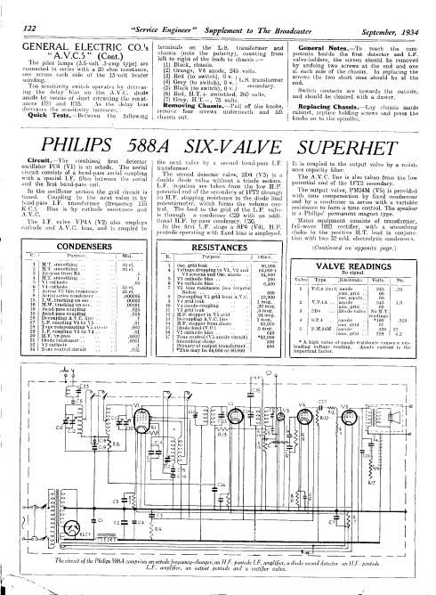
Circuit.~1lle combined first detector
oscillator F04 (V1) is all octode. The aerial
cilcuit consists of a band-pass aerial coupling
with a special I.F. filter between the aerial
lind the first. hand-pass coil.

In the oscillator section the grid (il'Cuit is

tuned Coupling to the next valve is by
hundpass LF. tritlisfol'mer- (frequency 115
]{.C.). Bins is by cathode resistance, and
:\.V.Q

The IF. Vlilve VP4A (V2) also omploys
cathode and AW. bids, and is coupled to

the next \iiilvo by it second hziuil-pnss IT.
transformer.

The second detector valve, 2D4 (V5) is a
double diode valve without it tl-iode section.
LFl inlpulszs are taken from the low H.F.
potential end of the secondary of IFTZ through
nil HF. stopping resistance to ills diode load
potentiometer. which forms the volume COH-
tlol. The feed to the, grid of the LE. valve
is through :1 condenser C29 with an addi-
tional HF. byrpflss condenser. C50.

In the first L.F. stage it SP4 (V4), ELF.
pvutode operating with fixed bias is employed,

CONDENSERS

s Hsistmncr

. ondcnsi-l . ,
l ug on use,
A, .trnckmg on on,
18 Hand-pass coupling
10 linllilvpdss coupling
28 Drcoupling A.V.C.linn ..
27 L.1I. counllug v4 to \
28 Tune compensating
29 LF. coupling v3 to \4 ..
30 ,h. =s ., . .
in Dind ldcuscr
22 l v2 cathode .
34 Tune control circuit


RESISTANCES
It.
1 05:. grid loin; ,. 50,000
4 Voltage dropping to v1, \ 2 rind 64,000+
v.3 screens and 050. anOLli: 64,000
5 v1 cathode bias .. 200
6 v4 nathode bias .. .. . 6,400
7 V5 [lids resistance («on Grncrlll
Notes) , . .. . .
s Decoupling v1 grid from AN.
9 Vi gridleak .. ..
10 v; mode coupling
11 \5 grid leak
12 l H r stoppir in
1.: . . :-
14 l 111?. stopper from diode
1.3 Diode load (v c.) , .
16 v2 cathode was .. .. .. 640
1? Tone control (\5 anode circuit) 0,000
Smoothing minim .. . . 500
l primary of output transformer. . 601)
*This may be 04,000 or 30,000

General Notea.-'lo reach the cum-
pononts beside the first, detector and LF.
valve-holders, the screen should be removed
by undoing two scrows at the end and one
at each side of the chussis. 1n replacing the
scruws the two short ones should be at the
end.

Switch contacts are towards the outside,
and should be cleaned with a duster.

Replacing Chassis.~Liiy Chassis inside
cabinet, l-opldre holding straws iind press the
knobs on to the spindles.

S UPERHE T

In is coupled to the output valve by a resist-
ance capacity filter.

The A.V.C. line is also taken from the low
potential end of the IFTZ secondary.

The output valve, PMZ4M (V5) is provided
with tons coinpemsation by fixed condsenser
and by n condenser in series with a variable

. to form a tone control. The speaker
. ps permanent magnet, type.

Minus equipment consists of transformer,
full-wave 1821 rectifier, with a smoothing
choke in the positive HlT, lead in conjunc-
tion with two 324nm. electrolytic condenlieri.

(Continued on'opposite page.)

VALVE READINGS

No signal.

\nlvni

1 Fol (uni) anode .
Iliux. grid ..
. osmnnodc.

2 l v.1)». .. .unode .
. uux. grl

3 2D: .. ,Dimlov

4 s It; a mile

mill
5

n lanolin
.aux. grid
* A high value of anode rennin» (limsts ll mis-

leading voltage Wilding, Anode current is thf'.
importitnt factor.

l

l

l

l

l

oT'éi l

i ,. I

The circuit of tho Philips 588A comprises an ociodefmguency-cfmngct. on HF. pznrodc I. F. amplifier. a diode second deleclor ml [1.17. penladc
L.F. amplifier, an output pcnladc and a rutificr value.

Page 2

l
l

September, 1934

Service Engineer Supplement to The Broadcaster

123

PHILIPS Quechua/A
SUPERHET (Cont.)

Lille all receiucrs produced by Philips
first superhel marketed by the firmihus a

number a] interesting features. A large

full-vision dial with changeable scales is

fitted together with a concentric type of
switch.

I
l
l
!

Lamps, Ltd" the model 588Afiwhich is the I

Special Notes.~0nly one diode anode is
used for rectification, the other being Con-
nected to cathode and chassis.

The biasing arrangement for the output
valve (VS) is a resistance between the centre
lap of the common filament winding and
Ellie. This resistance, R7, carries the cur
rent for the whole set, and the voltage drop
across this exists in addition to the ordinary
cathode bias between the cathodes and heaters
of the preceding anvcs.

Quick Tesla.-Between the terminals on
thn LS. transformer and chassis :-

Top (re-ll) H.T.+ smoothed. 228 volts.

Bottom (black). V5 anode, 220 volts.

Between the terminals on the smoothing:
choke (on top of the mains transformer) and
chassis :-

Front, H.l'.+ smoothed, 228 volts.

Buck, H.T.+ unsmocthed, 245 volts.

Removing Chassis.~llemove the volume
control) tone and tuning knobs (one grub
scrcw each). and the \vnverthange switch knoh
(twa gruh screws), and lift the chassis out.

General Noies.-If occasion does arise
when the set has to be reganged, the LF.
transformers must he set accurately to 115 KC
before the oscillator is touched. The adjust-
ment of each is very fine, and an accurate
modulated oscillator must he used.

In handling the set take care that the switch
lever and collar on the lever spindle are not
lost.

The mechanism of the switching is easily
followed when the chassis is removed.

The mnins plug is attachcd to the back of
the cabinet, and can be undone by removing
the two screws

Replacing Chassis.-See that the switch
lever is engaging in the grooved collar, and
that the rubber supports are in position.

Lay the chassis inside the cabinet: and
replace the holding screws and the knobs

The fact. that the switch knob appears to
no loose is not a fault. as the freedom allows
the grub screws to he reachell and is limited
when the tuning knob is replaced.

ADJUSTMENT

MAINS TRANS

@Ow

The chassis a] the Philips 583A is extremely
small for a 6-oalve set.
denser shown in the top deck " layout on
the right is a typical Philips miniature 1pr,
but the coils ingrlher take even less space.

Below is the diagvam showing hnu) the com~

patients are arranged below the chassis a] the

Philips 588A receiver, It will be noted

that all the trimmers are uccesslbly placed

round the Bilge of the chassis. These should

not be touched. of course, unless an accurate
oscillator ('5 available.

GD
0

@

a Q OSCTKTM BAND PASS TRIM?

TRIM IFTZ

The gang oan- @ GANG
COND. 3
8.
U)
m
E
SMOOTHING 2 IST
CHOKE g
IF.FILTER
le PILOT LAMP
WC) LIFTS OUT
Rl7
TUNE (TONE)
l RADIO MEASUREMENTS
Itadin Receiver Measurements. Roy l\l.
UARNARD, B.Sc., A.M.I.R..E. lliffe and
R17 Sons, Dorset House, Stamford Street,

London, S.E,1. Price 4s. 6d. (post 45. 9d.].

This book has been written as an encour-
agement and help to the service engineer
who is sufficiently interested In his work to
desire to leave the customer with a set that
is giving the very best possible results in the
way of both performance and quality of re;
production.

It deals extensively With equipment for
radio measurements and gives practical hints
on the gauging and aligning of the different
types of receiver as well as the methods of
combating the various forms of distortion.

Like most books on technical subjects, it
is a cmnpmmiee hctwccn the elementary and
the highly technical, and frequcntly fails to
differentiate between the practical limitations
and the ideal of quality reception.

The, details of design, however. are such
that with their aid the smvice engineer will
be able to luring a receiver to the upper
level " of standard limits instead of the
lowest that will pass.

The book contains fiftyrbhree illustrations
and diagrams and gives much useful infor-
mation in four appendices.