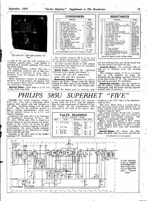
Philips 585 u service manual

This is the 2 pages manual for philips 585 u service manual.
Read or download the pdf for free. If you want to contribute, please mail your pdfs to info@audioservicemanuals.com.

Page: 1 / 2
left right
philips 585 u service manual

Extracted text from philips 585 u service manual (Ocr-read)


Page 1

September, 1935 Senate Engineer Supplement to The Broadcaster 73
CONDENSERS RESISTANCES
U. ( Purpose. ) Mfd. R. I Purpose. . l Ohms '
13 Series serial . . . .000015 1 V1 cathode bias . .. 300 (f)
14 Decoupling v1 grid . .25 (350) 2 Sensitivity control .. vnr. 2,000
15 v1 aux. nrid by-pass cl 2 (300) 3 v1 use. grid. harmonic suppressor 1,000 (i)
10 v1 cathode bypass , 4 v1 one. grid leak .. .. 00,0009)
17 V1 osc. grid reservoir . 5 v1 aux. grid ptl'. .. 40,000 (g)
13 Gram. feed from V: to V4 0 v1 aux. grid pu'. .. ., 40,000 (1)
10 v1 anode decoupling 7 v1 050. anode decoupling .. 100,000 g) .
20 v2 screen by-pass 8 Voltage dropping to V2 aux-grid 30,000 ( )
21 V2 grid decoupling 9 V2 cathode bias . . .. 00 (f)
22 v2 cathode by» ss ., 10 Decoupling v2 grid 510.0003)
23 In. feed 0; A. .c. diode .0001(350) u A.V.C. load ptt. 510,0008i
24 Hr. hyrpass from diode . mousse) 12 A.v.c. load ptl'. .. 510,000 )
25 . coupling .. .. . £54300) 13 Decoupling A.V.C. to v1 510,000)» ,
20 . byrpass from diode , 0001(350) 14 Hr. stopper in gram. reed 100,000 g)
27 H.T. smoothing . i . . el. 8 (450) 15 ! H.F. stopper from diode. . 100,000(})
28 an. smoothing ., .. e1. 0 (450) 10 . Diode load . I 200,0 0m
20 vs cathode bypass .. 01. 20 (30) 17 v.0. .. .. 0, 0
30 Part of tone compensating cir» 18 V4 grid Stablliser 20,000 (1)
unit . .. .. i. .. .01 (450) 13 ¥4 calthodclhlasbf. f .i'v c .. 338i
, , ,. , , , z xoviiingreay asor .. a .
L. , ,. , : w», _ , _ ., _ Biacketed figures denote unworknig Voltages. 21 Tom mépfilwmg w ode .. $358803
. Speaker 9 . i. .. , o s
The Lima 81 II (able nrydel salicylic! AC. ' . _ _ Bracket, gum, dam, Wm, mung,
four. _ [be variable resistance R2 is at the back

. . to that of V4, and the LP. coupling is a

resistance capacity filter. Tone control is
provided by a. variable condenser, -12, across~
the diode output. 1

The output pentode, A/70/C (V4), has a.
grid stabilising resistance and istoné come
peusated by a condenser in series with ii
resistance across the primary of the output
transformer.

Mains equipment consists of transformer,
full-wave A/ 11 [B rectifier, the speaker field
in the positive HiT. lead for smoothing, and
two electrolytic condensers.

Special NOEL-Pilot lamp is a. 3.5 volt
.5 amp. flashJamp bulb.

of the chassis and provides a certain amount
of control over interestation noise.

An extra speaker should be used without
a transformer and should have an impedance
of between 3 and 5 ohms.

Quick Tests.-Between the right-hand
terminals on the speaker and chassis :-

Outside, 450 volts, H.T. unsmoothed,

Inside, 275 volts, FLT. smoothed. .

Removing Chassis.iThei-e is no need to
remove the knobs. Simply undo the screws
holding the fibre cover on the bottom of the
cabinet to reveal all the under-chassis come
ponents.

When the chassis must be removed, undo

the four holding bolts, pull off the knobs and
free the speaker lead from the clip.

General Nolan-The condensers 021 and
C28 are of identical value and working

voltage.
The oscillator section of V1 is converted
into an L.F. amplifier for grain. by

switching the decoupling condenser 018 over
to the grid circuit of V4. The connection of
the pick-up prevents V1 oscillating.

Replacing Chassis-Lay the chassis in-
side the cabinet, replace the bolts, the cover
underneath, and the knobs (springs opposite
rounded sides of spindles).

PHILIPS 585U SUPERHET FIVE

Circuil.-The' octode frequency changer,
F013 met. (V1), has a hand-pass aerial
coupling with special coils and includes an
I.-F. filter. Oscillator tuning is in the grid
circuit. Bias for the oscillator section is
irqm a cathode potentiometer, while that
for the pentode section is by A.V.C. and
cathode resistance.

Coupling to the next valve is by band-pass
LF. transformer (frequency 115 kc.). The
LF. valve, VPISA met. (V2), is biased in a
special manner to rovide muting and ampli~
fication of the AHIVC by having the id
return taken to a. positive tapping on an .T.
potentiometer, the actual biasing potential
being controlled by the diflcrence in voltage
drop acroSs R4 and R10.

Coupling to the next valve is by another
band-pass LF. transformer.

The second detector, 2D15A (V3), uses the
second anode for AVG, and the negative
bias for noise suppression is obtained on the
first anode by the potentiometer R11
(mounted on the back of the cabinet top).

VALVE READINGS

13 volt Universal " val
Type. I Electrode

Volt

1 120.13 met. .. anode .J 100
Ingrid 65
oscianode 65
2 V.P. 13A . anode 180 1.5
auxgrid 00
3 2n13n.. .. diode - l -
4 hams .. .. anode 140 .75
5 Pen. 26. .. anode 167 40
l Jsuxgrid 90 5.5

Coupling to the L.F. valve is by resistancc<
capacity filter.

This valve, HLIIS (V4), is a triode with a
tone correction circuit in the cathode lead. It
is also coupled to the. output valve by another,
resistance-capacity filter. .

The output pentode, Pen.26 (V5), is stahii
lised by grid resistance, and tone control is
by condenser and variable resistance. This
speaker is a. permanent magnet model.

Mains equipment consists of H.F. mainsg
chokes in each lead, harretter lamp for theg -
heater supplies, half-wave rectifier, a choker
in the positive H.T. lead, and electrolytic
condensers.

Special Nolan.-To remove the pilot
lamps (No.8070) undo the screw and lift out.

(Continued on next page.)

A. noise suppressor
circuit is im: 11
in the Philips 585 U.
Some circuit varia-
tions are dealt with
winder General
Nola."

Page 2

Service Engineer Supplement to The Broadcaster

42 A
SM'TH'G CHOKE

\_/

=3 RII4)

W. GD 9
COMM .
ZNDBP

LF.
FILTERm/I

69 R27

@


Mallard universal value: are used and lead: to (he lane and suppressor Cordials are carried

IFTI TRIM

in heavy cables.

IFTZ TRIM

v

LW
PAD Dec; 2"

ce R7 $5
C V2 t==nv3 VVL
B as: (29 17;
SRBVklg 4: 6
L4
=

II/
I.

<4!
1::

lsr 8P TRIM 2w 8? TRIM. MW IRIM 05C.

NS
HUG
1

C4}

(146-3

r/

R2 J
. G9
. C7

%

@I

The mu! of resislars in the centre towards (he back of the Philips chassis are, in order from (he

oullfde; R's 2|.28, 20. 1.9, 4, and 3. .

RESISTANCES CONDENSERS
R. Purpose. Ohms. C. Purpose.
1 Rectifier stabilising resistance 4 x800 (l) 1 H1 smoothing . . r . e1.
2 Voltage dropplng touux. grids 2x 40,000 2 1111. smoothing .. .. el.
1 3" Aux. grids lay-pass ..
3 v2 Mu ptr. moss nxr. . Amsg. a) 4- v4 anode decoupllng
4 v2 blns per. across HIT. . 30,000 Ii) 5* V6 aux. grid by-pass
5 v4 anode decoupling H .. 20,000 (u 6 v1 cathode Ivy-pass ..
6 Voltage drop ing to V5 aux.glid 16,000 (1) 7 Deconpllngtllulng meter
7 V1 enthode la! ptr. . . . 250 ( ) 8 V2 grid decoupling . .
8 V1 cathode bins ptl'. . . 160 ( l 9 V2 cathode bypass
9 Decoupling v2 grid . z x 5 meg. 10 HI. by-psss .. ., ..
m 11 V4 cathode by-pnss .. e1.
V2.mthode blns I . r . 5,000 (l) 12 V5 cathode by-pass . . el.
Norse suppressor control . 50,000 20 Band pass coupling . ..
v4 cathode Mas ., .. 5,000 (l) 21 Band pass con ung
V5 cathode M88 . . 320 (l) 22 Low. 060. hanging
Volume control .. .r var. .5 meg. 23 MW. osc. tracking
Decoupling delay bin feed . .53 meg) 28 RF. lay-pass ..
nr. stopper ., .. . .2 mag) 20 LF. feed to A.V . diode
\'1 grid decoupling .5 mag) 30 ILF. lay-pass ..
u use. gnd leak .. 50,000 m an L3. coupling VA to v5
A.V.C. feed to V2 . 2.5;3. a: ggneocontrol circuit r
no compensati ..
A.V.C. diode load .32 mag. 34 E!» LS. feed H ng . r
( ) 35 Ex. L.s. feed .,
v4 anode, LI. coupllug . .2 mag) 37 LF. coupling to v4
V5 grld leek . . . . . . .34 meg. 88' Sella earth r .
V (l) 39 Serio- aerial . .
\ 5 grkl afablllser (lnsldc lead) . . 1,000 42 Rectifier stlbiliscl'
Put of tune control clrcnlt . 100 (H 45 M. RU. lead ..
Part of tone control clrcuit .. $0,000 47 v1 grld decoupling .,
Across sens] Input . . .2 meg. 48 V4 cathode by-pnss . . el.
A.\'.C. feed to V1 .r .5 megrfl 49 M. RU. lend .. . .
Bracketed figures denote wattage rating. 50 M7 bur-ms -» .. -
* May be 04,000 or 80,000 ohms. * In condenser block. Code No. 23100000 3.10.

September, 193.5

PHILIPS MODEL 585 U
(Contd.)

The Philips SBSU is a five-value plus
rectifier and bundle! receiver fur AC.
DC operation and includes a number of

interesting features.

the insulating bracket. taking care not to
drop the washer.

Quick Tech.-Between the two terminals
on the output transformer bobbin and
chassis :-

Front (red , V5 anode, 167 volts,

Rear (bla ), H.T. smoothed, 1.90 volts.

Removing Chm-aieremove the knobs
(grub screw) and the wavechange lever (two
grub screws).

Release the cables from the cleats, and,
after turning the tuning V) minimum, release
the band from the clip on the pointer (to do
this, ease up the flat spring on the clip and
all the stud out).

ltemove the insulating covers over the
holding screws and remove the latter. Un-
solder the leads from the tuning meter ter-
minals. The chassis can now be withdrawn
for examination.

General Noles.--The disposition of the
components may be slightly different in pro-
duction models.

In some, R25 may be replaced by a choke
mounted as shown in the diagram (under-
neath layout).

052 may be mounted between CS4 and G35
in the same diagram. In other models it will
be found on the tone control R26.

The condenser 050 and resistance R17
shown in the lay-out diagram near the
volume control may be absent. These are
connected between CS7 and R14 and prevent
overloading with the volume control at
maximum.

The oscillator padding condensers and the
LF. transformer trimmers are double con<
densers, one section being adjustable from
the outside and the other from the inside.

Replacing Chanda-Lay the chassis in-
side the cabinet, taking care that the rubber
bushes are in position. Place the enrthing
plate between the right-hand rear corner
(looking from the back) and the screening foil
on the inside of the cabinet.

Replace the holding screws and cli the
leads and the condenser driving and.
Replace the knobs and the insulating covers
on the holding screws. Revsolder the meter
leads, red to the right (from back).