Philips 555 a 2 service manual

This is the 19 pages manual for philips 555 a 2 service manual.
Read or download the pdf for free. If you want to contribute, please mail your pdfs to info@audioservicemanuals.com.

Page: 1 / 19
left right
philips 555 a 2 service manual

Extracted text from philips 555 a 2 service manual (Ocr-read)


Page 1

STRICTLY CONFIDENTIAL

FOR APPOINTED PHILIPS
DEALERS ONLY

COPYRIGHT 1938


AFlCHlEF

DOCUMENTATIEDIENST

NJHR

A1

ID IH ll IL ll IDS

SERVICE

MANUAL

FOR RECEIVER
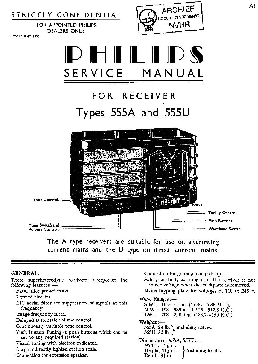
Types 555A and 555U

Tone Control.

Mains Switch and L
Volume Control.

Tuning Control.

Push Buttons.

1 Wave-band Switch.

The A type receivers are suitable for use on alternating
current mains and the U type on direct current mains.

GENERAL.
These superheterodyne receivers incorporate the
following features :--

Band filter pre-selection.

7 tuned circuits.

LF. aerial filter for suppression of signals at this

frequency.

Image frequency filter.

Delayed automatic volume control.

Continuously variable tone control-

Push Button Tuning (6 push buttons which can be
set to any required station).

Visual tuning with electron indicator.
Large indirectly lighted station scale.
Connection for extension speaker.

Connection for gramophone pick-up.

Safety contact, ensuring that the receiver is not
under voltage when the backplate is removed.

Mains tapping plate fOr voltages of 110 to 245 v.
Wave Ranges :-

S.W. : 16.7-51 m. (1196-588 M-C.).

M.W.: 198-585 In. (1515-5128 K.C.).

LW.: 708-2,000 m. (42357150 K.C.).
Weights :-

555A, 29 1b. including valves.

555U, 32 lb.

Dimensionsm-SSSA, 555U :~--
Width, 194} in.
Height, lli in. Including knobs.
Depth, 9% in. }

Page 2

Types 555A and sssu A2

DESCRIPTION OF CIRCUIT.

Short Wave.

Aerial circuit: 812 inductively coupled with 313.
Grid circuit of L1 : 813, tuning condenser C8 and C32.
Oscillator grid circuit: 518, tuning condenser 69,
'd condenser C29, grid leak R6.
scillator anode drouit: S29, R25.

Medium Wave.

Aerial circuit: 56 coupled
capacitiveiy (C14) with 58.
Band filter: lst circuit: 58, tuning condenser C7.
trimmer C10, coupling condenser C16, coupling all
530.

2nd circuit: Coupling condenser C16, coupling coil
83]., $10, tuning condenser C8, trimmer C11.
Oscillator grid circuit: 814, tuning condenser C9,
trimmer C11. padding condenser C20.

Oscillator anode circuit: 515, R19.

inductively and

Long Wave.

Aerial circuit : 86-57 coupled inductively and
capacitively {C14} with 88-59.

Band filter : lst circuit : 88-89, tuning condenser C7,
cou ling condensers C15-C16.

2n circuit: coupling condensers C15-C16, 810-511,
tuning condenser C8.

Oscillator grid circuit: 514, $16. tuning condenser
C9. trimmer C12 [(331). padding condenser C19 (C20).
Oscillator anode circuit : 817, 515. R19.

Note.-In the M..W. and L.W. ranges C29 is short-
circuited and the padding condensers serve as grid
condenser. R14- prevents parasitic oscillation of the
pentode of L1.

Image Frequency Filter.

C17 together with the let circuit of the band filter
forms a filter for the suppression of signals at a
frequency which is higher than that to which the
band filter is tuned by twice the 1.F., these voltages
being prevented from reaching the coupling con-
densers or the mixer valve.

LF. Circuits.

Aerial filter : 529, C37.
lst Band filter: 820, C21, $21, 622.
2nd Band filter: 522, C23, 523, 524, C24.

Detector Circuit and AI. Amplifier.

The first anode of the diode L3, cathode. R10 (volume
control), R8 and 524 comprise the detector circuit.
(325 short-circuits the H". from R8 and R10. The
A.F. voltage across R10 passes via C26 and R11 to
the grid of L3. C27 diverts any residual IF. voltage,
R11 prevents oscillation of 1-3 and 325-326 is the
speaker transiormer.

Variable Tone Filter. R17. C35. R18.
Automatic Volume Control.

The second anode of the diode L3 is connected via
C50 to 822. producing a direct voltage across R5
which is proportional to the signal strength and
which controls the amplification of L2 via R9 and C5.
and also that of L1 via R4». The control is delayed
by the voltage across R13-R15.

Visual Tuning.

A portion of the direct voltage rectified by the first
anode of L3 is taken fiom the potentiometer Rfl,
R23 (C41) and passed to the control grid of L5. On
an incre ' Signal str th the negative bias on
the control grid of L5 also increases, with a reduction
in the anode current. The potential difierence across
R24 thus becomes smaller, i.e., the potential difierence
between the screen of L5 and the deflector plates
connected to the anode is reduced. The screening
effect of the deflector plates being thus reduced, the
width of the light bands on the screen becomes

greater. The receiver is correctly tuned when the

width of the green bends reaches maximum.

Feeding .

Mains transformer SI, 82, S3, S4.

Ripple condenser C38.

Smoothing filter Cl, 341. C2.

Voltage for grid 2 of L1 : via R3-C4 and for grids
3 and 5 further via, R21-C40.

Anode voltage for L1 and L2 as well as screen voltage
for L3 and 1.5 : direct from C2.

Screen voltage for L2 : via RED-39.

Anode voltage for L3 : direct irorn C1.

Anode voltage for I.5 : via R24. '

Push Button Tuning. See G sheets.
Receivers for D.C. Voltages.

NOTE :--Fig. 11a shows the difference between the
U and A types of receiver. Reference should be

made to Service Manual for Converter Unit Type
7880Cf78816.