Philips 523 ub service manual 2

This is the 2 pages manual for philips 523 ub service manual 2.
Read or download the pdf for free. If you want to contribute, please mail your pdfs to info@audioservicemanuals.com.

Page: 1 / 2
left right
philips 523 ub service manual 2

Extracted text from philips 523 ub service manual 2 (Ocr-read)


Page 1

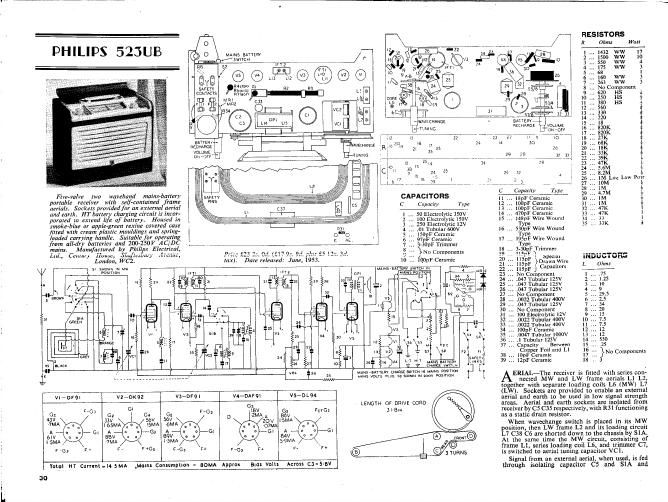
PHILIPS 523UB

Five-valve two waveband mains-battery
portable recziver with s'eIf-cuntained frame
aerials. Sockets provided for an external aerial
and earth. HT battery charging circuit is incor-
porated to extend lift of battery. Housed in
smoke-blue 0r apple-green rexine covered case
fitted wtth cream plastic moulding: and spring-
Iaadcd carrying handler Suitahla for operating
from all-dry batteries and 200-250V AC/DC
mains. Manufactured by PI
1214., Cam, mm, 51.19%» ',1

London, WC2.

' RESISTORS


i1 '4' £23 2... Cd. (5!"
tax). Dare released:

9.5, 93",
June,

lSOpF Ceramic
97pF Ceramic
. 3-30pF Trimmer

Nu Camnanents
i
. 100131: Ceramic

oanom

s1 snow». w w
_vos1r1cm

T19

z

£a1~s»anwsk7 s1

mws unmv
r 01:th Evil'h,x

mmsrnnzm cHARGL 5mm in mm posmou

MAINS vous

r 65

Total HT Cumnl- l4 SMA ,Malm Consumpuon

= BOMA

Appm am: Volt:

Across cs - 513V

30

mm 59 swam IN 1001/ POSITION

LENGVH OF DRIVE CORD

SlIBw


Type
l7 I9SpF Wire Wound

R Ohms Wan
MAINS antam 1 .. 1432 WW 17
swnm 2 .. 1530 ww lg
' 1FT2 # 3 .. 55 WW
)2 E 1:11 4 . 175 w 3
V. @ L10 1 5 . as I
L13 1.12 L11 6 160 W 3
1n 7 , 2.53 w 3
FEW sci-3?: m 3 3 s No Component
cowcrs mmm 9 620 HS 1
11/1121 1 HS
FE r z /w:2 8 o 250 HS E
R54 I a
<2 i l sv/a 5 12 53 l
. cm L7 61 i i
c: 1 L14 L'S vet {WM/[CHANGE ~ 5111151111 1
1*1 "NW, HKHARGE voiuw 1
- 1 l i 1 d v ~v oN-orr g
- LV \ 1 12 11 22 fi~723 27 11 q' .0" g
BATTER

aecmmgi. I: |-] AVECHANGE 1s 30;.) 5 17 24 4 30 i
mum: .R 21 35 25 21, t
0M": &*i M9 2? PS 32 9.1 i
E . , 1 i '12 2614 no Ia l1
1 011 as 3 g i
1 1 Ci 7 1a 24 3 29 Jr a E g
17 1a 13 1 ~ : atr
c,1_b__ a- 747*,7, , , ,7 N, j , x, ,7 1 1
C Capacily Type g
CAPACITORS 18pF Ceramic l
C Capacity Type 100pF Ceramic it
-~- 1001:}: Ceramic 1
1 . 50 Electrolytic 350V 470pF Ceramic 1
2 . 100 Electmlytic 150V . 148pF Wire Wound , 3 1
3 . 251) Electrolytic 12V Type 35 33K 11

4 01 Tubular 600V 16 530pF Wire Wound

1

we . _
S-JGpF 1 nmmer
v: i
:pcclal

Drawn Wire
Capacitors

. llSpF

. ll5pF
No Component
.047 Tubular 125v
.047 Tubular I25v
.047 Tubular 125v
No Component
.0021 Tubular 400v
.047 Tubular 125V
No Componcnt
100 Electrolytic 12v
.0022 Tubular 400v
.0022 Tubular 400v
IOODF Ceramic
.0047 Tubular tooov
V .1 Tubular 125v

. Capacity Between

Copper Foil and L1

38 lODF Ceramic
39 12pF Ceramic

No Components

11
2.
3.
4
5
6
7
8
9
0
l
2
3
4
15
16
17..
IE .

ERIAL-Thc receiver is fitted with series con-
nected MW and LW frame acnals L1 L2.
together with separate loading coils L6 (MW) L7
(LW). Sockets are provided to enable an external
atrial and earth to be used in low signal strength
areas. Aerial and earth sockets are isolated from
receiver by C5 C35 respectively, with R31 functioning
as a static drain resistor.

When wavechan a switch is dplaoed in its MW
position, then LW rame L2 an its loadin circuit
L7 C38 C6 are shorted down to the chassis y 51A.
At the same time the MW circuit, consisting of
frame Ll, series loading coil L6, and trimmer C7,
is switched to aerial tuning capacitor VCl.

Signal from an external aerial, when used. is fed
through isolating capacitor C5 and 51A and.