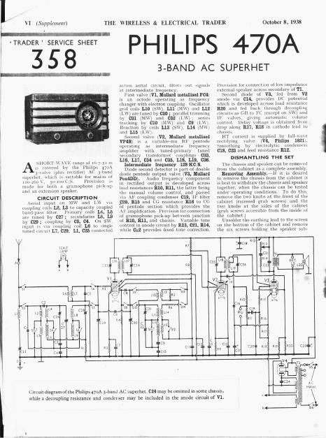
Philips 470 a service manual 2

This is the 3 pages manual for philips 470 a service manual 2.
Read or download the pdf for free. If you want to contribute, please mail your pdfs to info@audioservicemanuals.com.

Page: 1 / 3
left right
philips 470 a service manual 2

Extracted text from philips 470 a service manual 2 (Ocr-read)


Page 2

October 8, 1938

Under-chassis
view. Diagrams
of the rwu wave-

l change switch
i units are over-
leaf C32 is of

the wire-wound
adjustable type.
L1, belonging to
the aerial IF
filter, is the only
mil beneath the
chassis.

THE WIRELESS & ELECTRICAL

hullll: to the front of the cabinet, when L ie

msemhly can be Withdrawn
Wily; rzplucm

, do not for

gel t0 Nave

the metal plates on the top middle al ri

hottoiii rightrhanll

fixing
. note that the knobs

5Cr.~\\>
With white circles

him]

go on the spindles at the front.
Removing speaker.~1he spetkei' uln
be removed from the cabinet by UnSOldk' -

mg the leads, slackening the
holdingy it to

nuts gm rl washers}

three clam} '
the subrbaffle

(m ts, lock

and swivellllig tllt'l 1

out of the way, "View replacing, see that

the terminal panel
(OHHCCL the leads

is on the
as follows, numbering

left «And

Ill-0 tags from bottom to top:~l and .5

Joinitl together, leurl
output transformer
scale assembly; 3.
no output transformer.

ttfiNDL Slilxi

lilingr 9000.000

:00 .. .
-\url.ll rm. sw 1000...».
w 1100.00.00 .

~, 0d v.10.

u. .-0...le...~. r

W cm-uu l W in} v.-

llt. .zrcun MW tinrkc

\l ..~v:.
rwllpllllg

\ _v (let-00010...

\ a h!) tierollpllng ..

k5 lplmg in \'3 l\\'( diode

0.0.000 1.00.0 .

l upm

\' , muhml.» M500»

l'.ul HT smrmthlntv 5.

A .~0:.pl...g .0 i. . 0.0.x.-
. ms:


worm-.0. ..
0000mm .
RF by runs .
him 100...:

. luv-.1 :0.
l: t T

.-002\.>0;

nu... 0. 1.... 1.000: .

Hind puss 50.; tuning
, m lliltorclrrllittllullig
(is ,ull MW ililnmcr
, w... my 0.0.0.0.-
.0. ll 0005, 00, 0.00.:
.0. W 0.0.5, 500 0.00.:
:nd [F (runs. pn. tuning
20.1 H: «0.0:, 500. tuning


4.09"..4 9
,5

liT/MJM"

MW and LW aerial 00001005.
5.0.0500. mummg 000.10..-

0..0.l0 1.04 5(. 0'0.

IrlillliP [0th Control

l 0mm: 0... MW {0.00.00}

13.001015: «e1 .\lw 000.00. I

to top stud on
and oarthing load in
lead to bottmn arm

COMPONENTS AND VALUES
\

90009.
WUUOOX

. 4 oxfi
95
. 95
9099...
5099,-
0090, l

l
l

u l
0 05
0 05
0 00000.
n 15
n 70....K
:5 )
12-

l

0-. .0:
31"
0-. z
.1 . 00.
0 . 000;
0 000 0,
01.300;
0... m m
0-0000.
000003
0 0 mo 1
-0 .0.
0.0 t...

. 1 00m

0-0. 0.
i Flu r. t

l Val'les

[HZSIS] Axclr 5 (0mm;


lil \l. [mum to 000000100: .0000.»
R2 v. u; stabiliwr . 50
R3 l V. fixed GB mama... » 050
k. \'. cu mistam.» 50,000
kg, l 0.x 00000.. 00.00.00 . 10,000
l<0 . and LW damping ,, 500
K7 . (isand VI 0... 01¢ 1 0,000
Rt H1 .000 mutanccs (l .2500
l<., v; hxrrl (.ll rmsmuct :50
Rio Pm v; gnu 0.0.ie 10ml . moon '
Ru in... V; signal diode l0,..l
.00....01volumecunu-ol , l 300.000
R12 HT .000, except. .0 v.1 000.10,, 2.000
Ki . ramble tone .10....01 . . 50,000
in; Part 0......1010 {our 000001 .. . .00
R15 v grid 3.0000. ,. .. .0,000
km in; lEMSIRHCC . .. 1,000,000
H17 (.13 ;....l AVG (1.1., .01 5. .00
R18 .010 .mlstmces 4 mo
km AVCllnevietollpllng ,. 3.000.000

7 v. A n, rlflle 109.0 0.0.000

tlllllzR (UMIWVENIS

5.; 7.70170: 00..

, l.. .
1' ~' 0.01 MW and lw 00.01.00 4"
9x _ .1 .
I , LU]: . , . .
I; l 5 500.150.. pumary r... t
l 0 Aerial sw 00001.00 00.. ,
l 7 dorm] sw 20.00.; 00.1. i, .
l i ; . Bnndqmn secondar) rink l .1:
. l..0 \k Circuit. Vl....0.g ~ .l l 0-.
l... 05.; .00.. MW 00...... 00.1 ..-0
Ln ()St 01mm LW «0.00.; toil . ;_. 0
Lu l mullaiorswmartiunmil .1 l i 4
1, (00.11.00. Mvt'rcartloul'oll ,, 7)
I45 Usrdlanu l.W macnm. . oi]
l .n .

, lsl IF trans.

l :h . . 5 _ ,1 ln' _
L) l 200 ii. 1.00, 5 _.8 .30-0
l.:n Speaks. spnechcull .. 4 0
T. 1 00:00: .00..» {£3 23
,1»... 10...] -0
['1 . Man:V Caitr «8. 0'!

mm

VALVE ANALYSIS

\CthL. voltages and currents given in

the table (col 3) are those measured in
our receiver when it was operating on
mains of 227 V, using the 220 V tapping
on the mains transformer The receiver
we tune-d to the lowest wavelength on

TRADER

VII v

(Supplement)


the medium bnnil and the volume tontinl
was at maximum, but there was no signal
input.

Voltages were measured on the
scale of
chassis

.100 \i
a model 7 Universal Avomete
being negative.

\ \
( 400d. l Anodi- . 50.00..

iten
Valve Voltugn l Luneni Voltage Imrreut .
(V) l (0m) m 004,
l I an ,
\l. H, 5 00 .l lalot .00 l l 0
:15 l
\ \l'pll :35 77 .m _, 7
glmlflfl) l :04 . -0 1 s < x
V: m. ~7~+ 7


1 hash ..0000, AL,

GENERAL NOTES

Switches.¥SI-Sl4 are the
switches, ganged in
beneath the chassis

wa veba nd
two rotary units
These are indicated


'. and shoun in

View.

The table (page VIII) gives the switrh
positions for the three control settings
starting from fully anti-clockwise. \
dash indicates open. and 0, closed.

815, 816 are the 93113 mains switches.
ganged with the volume control R11-
and as indicated in the uuderichassis
View, they are at the front of the volume
control.

Coils,~L1 is beneath the Chassis, and H
unscreened. 1.2-1.5; LB-LB; L10-L15;
and the ll transformers L16, L17 and
L18, 1.19 are in t ,e screened units on the
rhassis deck. Each unit contains one
trimmer, additional trimmers, in the
case of the IF units, being,7 mounted
nearby, on the chassis (luck.

Scale Lamp: This is at Philips MES
type, with a frosted bulb its part number
.< 8042-07.

External Speaker. Two sockets
provided at the rear of the chassis for a
low impedance (570) external speaker.

Condenser 032 -1lu's is a ere-Wollnd
adjustable type.

annulled owlmf