Philips 462 a service manual

This is the 4 pages manual for philips 462 a service manual.
Read or download the pdf for free. If you want to contribute, please mail your pdfs to info@audioservicemanuals.com.

Page: 1 / 4
left right
philips 462 a service manual

Extracted text from philips 462 a service manual (Ocr-read)


Page 1

IIIIIiIIIIIIIIIILIIJIIIIIII IIIIIIIIIIIIIIIIIiIlIIIIIIII|.I IIIIIIIIIIIIIIIIIIIII IIIIII IIIIIIIIIJIIIIIIlIIIIillllIIIlIIIIII IIIlli IIIIIIIII I IJlllll I III Ii

TRADER" SERVICE SHEET

817

IlIIIIllllIIllllllllllIlIlIllllll'lilillllllllIIIIIIIIIIIIIIIIIIIIIIIIIIIIII llllllllllllllllilllllllllllllllllllllllllllllllllllllllill IIIIIIIIIIHIIII IIiIi

HREE Continental type multiple

Valves with Lot-till ' b on {re

used in the Philips 402A supuihit,

with a Mullaid outnl based l'cctllll, lhivf

(lotiiiL urt given overlniif, and butt dim

gmim u'o insrt, on the right oi il]( rii'oiit
diagram below,

The three wiiveliands are 162-52 in,
190,575 in and 8002,000 m. aid the re,
(0' or is designed to operate 1mm A Li
in; us of 1007260 V, 507100 c
I Release date and original 1mm: Mun/i.

1947; £18 183, plus 14 lg 41! [HUG/Iiiw
I tar.

CIRCUIT DESCRIPTION

Ai-iizil input on NV. and L,\V. rid L1,

L2 and 02 to mixed coupled hundrpiiss

liltvr. Primary (oils L3, L4 iiri tunvd by

l 030, and somndnry coils L1, L8 by [2113.

('oupling hy'capacitors GI (M Kl. and

ca ([i,\V.) in conjunction with Coils L9,

L10. Tnnige rejection by on on s w,

input ix no coupling coil L5 to single
tnnwl tircuit L8, 033.

'u
I-
Z
m
>
- m
E
)>
I.

iiim willie (v1, Mullard Ecim) ii a
trimle Iii-mung npeivaniig in ri-i-iliinii-y
i
I A
I

Supplement to The Wirelesr ('9'
EfiiicflJlaififijfle 2331917

HILIPS 462A

3-BAND

changer 'itll injector grid coupling be-
twman llimli-I and implode sections.

Triodc oscillator anode coils L15 (S.W.),
L16 (MAN) and L11 (li.VV.) are tuned
by can. Pniiillel trimming by cs1 (S.VV.),
638 IM.\V.) and 012, C39 (Liv); series
tiarking by C11, C35 (MiVVJ and 036
(L.\\'.). Tracking on S.W. by 084. Re-
illitll) coupling by L12 IS.\V.)> L13
I.\I.W.) and L14 (li.\V.)

Second \alve (V2, Mullard ECH11) is
another tirimle heptode. in which the hep-
turle :m-tinn operates as a variable-run
lllltllllttliulk h-equemy amplifier with
tunedrpriinai'y. tunedrsecondary trans
iormcr couplings 01, L18, L19, cs and
015, L21), L21, 016.

Intermediate frequency no kn/s.

Hindu nm-ond drtoctor is part of douhle
diode pvntudp output \nlve (V3, Mnllard
EBLri). Audio lleqmllly L'mnpouent in
rectified output is developed across
manna] volume control RE, which acts as
diode load renisiur, and passed via AiF.
coupling capacitor (:18 and CG, resistor
R6 to C . of V2 triudu section, which
()lJl'latPS d3 AiF. anipli LF. filtering
by R11, 610 in diode Cll'L'lllti.

A.C. SUPERH ET

lrnviniuu l'nr llnA (innnvulinn of a grinne-
pininu llll'kvuli across Ra by "it as of
3119! Al sockets; one )1. which is associated
with sink: 315, 811. When the pick-
up plug is i Mail 316 ope-us to connect
llie shunt resistor R11, and S17 closes to
mute radio.

Second diode of V3, fed from V! anode
via. 019, provides 11.0. potential which is
developed across load resistor H18 and fed
back through decoupling circuits as G,B.
to Ft. and l.|<'. valves, giving automatic
volume control.

Resistance-capacitance coupling by R14,
021, R15, R16 between V2 triode and
pcntodo section of V3. Variable time con-
trnl by R15, 023 in CI}. cii'ruiti, mid fixed

- inn in anmle Circuit by cu.
appearing across the second-
ary winding of the output transformer
T1 are applied to ii frequencyrdiseriminr
ating network L22, L23, R9, and the Volt
ages developed across H9 are fed back to
V2 trimle (LGn circuit in opposite phase
tn the input signals, giving negative feed-
back, Piovibion {tn the connection of a
low impedance lKVl/Plnal spraker al'lOSs the
secondary winding of 1-1.

H 1'. Current is supplied by full-wave

R2

LIB
cs
-(7 'I'
m

R4 n5

L70

a
i

- "METACLIZEHEKEE SCPEEN

S7

RI R3

it

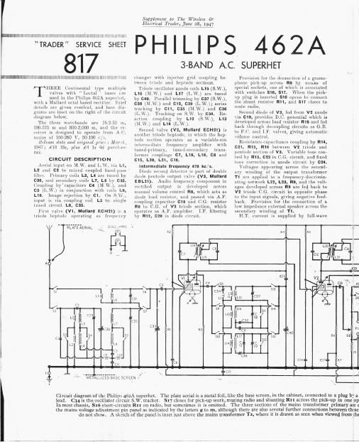
Circuit diagram of 1hr Philips 462A superhet. The plate aerial is a metal foil, like the base screen, in _Lhe Cabinet, connectgd to a plug by a
lead. C34 is the oscillator circuit S.W. tracker. SI7 Closes for pick-up work, muting radio and shuntng RIx'across the pick-1113.111 one up
In most chassis, 516 short-circuits Ru on radio, but sometimes it is omitted. The three sections of the mains transformer pnmary are g
the mains voltage adjustment pin panel as indicated by the letters g to m, although there are also gaveral further connecuuns'between Lhtse

do not show A skstch of the panel is inset iusr above the mains transformer T2, where it is drawn as seen when Viewed fromzhe

Page 2

Supplement m The Wirezm -1- pH1L11>s
Electrical Trader, june 28, 1947 1


L1 1 U»- . M. 101111111111 coll

462A
COMPONENTS AND VALUES
7 7 W, 7777 i 177 - 7 V V 777 7777 V 1
(AlACl'l'lHlS RESISTORS Vuluca
1 (111mm)
111 - 111111111 11111 . 1 00110012 1cm 11.1..1111101 .7 820,000
(72, Ae1iul"mp numb 0 00001 ..G H. T. f . . 23,1101"
1:; 11. 1.1 . 11.1» Hullllillg{ 0-01 BUG re 5101 1 47,000
1 111 11111-110 0-0-10 111 11110110 H T lwd 1 22,000
05 1 111c111.<0..01111022 .11 l . j 210000
1111 1 0-017 , 2 ,200 000
1 (7 11-00010: KT 1 V2 1110110 ..B decouplmg 470,000
1:11 1 0110010 11: Manual \olumc mun-01 1 700,000
1 C9 ( 1: 11111011101 U-llljnll [L9 ' * {Bed-bark shunt 22
. 1 110 111111 11110111111111 114017 1 1110 1 . .1111e 001-0111111111; 1 1,500,000
The appearance of the thps 462A 111 111.\\ fixmltluckor 00002111 $1 1 fig: pshlmt 10011100
- 111111 05121.. 11. 1111111111111 , 0000027 1 1110111101 1,000.000
superhet. The 313$ scale Pulls Stmgh 1 7: v1 1.. 1111111 111111111111; .. 11-00017 1111 V 011?. HT decoupling 100,000
out for dlsmanthng. 1111. V2 5.1; decoupling . 0017 1 1111 rlulle 11111111011111 100,000
81:. }..ml 1 1.11111151011110111'211 11-00010: 1 El} Enable 20111100111101 , 50011180
. '. (1 1.1110112 mparimn 00110102 i 1 1 111 s 011901.. . 1 120,1 0
recmfymg valve (VI, Mullard A131). »0 7 121110111. 011 111-1011111111; 11.017 1117 1 11.121u100111111gmm.» 1,200
Smoothing by rcsismr R11 and electro- 18}: 3211011081,[1111111111111 11-01 11:11: 1 V1. 3VV' 13?le 102111 .1 820.001;

. - . .- ' . 11111 1- 00111 mg 11011000: ' ., x9 11m ::
13"? Imam cza, cz1,_1e>1dual hif 30201.11 01.1.1 mum-i101 0000011.; R111 l} ,1.v. 0.110111 rem-mu {1 05
bemg neutrallzed by passmg Lhe ILL 1 (1.21 A [1. coupling 10 V3 pent 11-11-12 1

. ..,., , . . h
current lmugh_ 1* 110111-101} 0} Lhfi ouépllt- 21,25 10112201113151:decoupling 1:83.10 . Twu 17,0009 10.1.1011 in parulh'l
transformer pnmarv w1ndlng. leed 1 '-
, - v 1 121 Flu-11110111113111 1 11.001
(1.13. for V1, V_2, V3, and A.V.C. delay 1 (125* 1'1, w. 1311.11. 11 71, 1250-0
voltage, 5 Obtain from the-film!) liking 1 }H r 51110011011111mm-n
reslstors R19, R20 1n the H.l. negatlve
lead to chassis. Mains RIF. filtering by . 1 1100-505 . 1 V 111101.-
028. | Band-11m:1111111-11111111111 1 h 1.1)M11111 5 (mflg 1
The mums transformer T1 primer) is 1 4111121!11111.IW\'\m:li;n:-111138833: 1 . r l
1 Wound in three isolated chLlons which ale b 54 undarytuniug 1 fl 1 L" 1 111 11 "L-- mml' { 10011
w 1111-11-1» 0111102 1 1,2 111 01.11.1111; cuil»
brought out to seven Connections lettered ,- 1 _ 1 1 LK 1
. . . 1.1110101 1 000112 1 , 15111117113115 primary mil { 1
g, h, I, 1, k, I, m on the malns voltage truck 00002 L. . . .

. . . , 1.1 Aenzll m .cmlplnm1mll . 1
adjustment panel. A rotahng cap on the '11. 17l11l11l1rr 118338: L11 1 11011111 SAY. 111111111; cull . 1
Panel permms most mfflns Rages bc .1,\1 H'lmml-r 1100005 %3 3111111711113: 1111001111111) <-n1l.«{ 1
tween 100 V and 260 V to be accommo- ()s11llamrr'in-uit(11111112 - 1 13 ~ 1
dated by lnterconnerting 1.1m. comm pins if . 1.111 1110.111...- 111111111111 "1" 1
on the panel. * lellluLflil, 11111-111111. :Inuut, 1.11 1 051.8 ctionstnbillzcr 1

1.12 1n. . r11u'11011 0011 1
1
1

1/1 .,2 1,11 0. . 1,.\\ 101114.10 roll
1- 1 1,10 tuning mil
1.11: 111111111; 1011 , ,
1l 17 1 .1, \\ 1111111111 «.11
1.- 111'.
1.111 l 1 I Am- . .11.:11 1
1:111 [21111.11 11101.1" 0 E
1.22 11.111101111111111011-111- lmfik l
1 . 1,23 1111 uir. .
I-fi 121 511-11111 spu-ch coil 1
, . 1 .
11 .
Jz

110m w-
total

.1,

VOLTAGE

11010517111111 E
PANEL (i
1 Reverse s\1d:)

(1yan1"sm'ilr'll1s . 7-

M: 1n~ M\'il('l|~'~, 1111110111 15

0:1
VALVE ANALYSIS
11le volumes and currents 1211011 in the
table lvelow are those quoted by the 1111111111115
Lure! vrvho live the unsmoothcd 1LT. Voltaire
lls f1 .
Annm- 3.1110111- N'rm-n m-m-n
\hlVl Vulmuc (ulltm \nlmul ('llnnl!
("1 (11111 1V1 (111A) 1
. . 1-1
\I IuI'HA ()~(illntva 6'0
1 115 4|)
gbf a flflqble A c MAINS W 1 1'H { 2'). (0
me operatmn.

y an: connected directly to the seven pins on
1th tse pins and others on the panel, which we
)5)? 1h: inside of an inverted chassis.

. , .. 1110011 3-11
. 411 1 11 1

\1 lfilFLZ 245 ., 1 715

\1 .\/,11 211111 7 1 7

' 14111011 411111110, ,\ 1