Philips 400 a service manual

This is the 4 pages manual for philips 400 a service manual.
Read or download the pdf for free. If you want to contribute, please mail your pdfs to info@audioservicemanuals.com.

Page: 1 / 4
left right
philips 400 a service manual

Extracted text from philips 400 a service manual (Ocr-read)


Page 1

(3mm

,~-f\/

i 3 11"

[\ll iiplitu aim-ii. This nice dim llJéeL l.- ulie navy"
liJIlI at THE Winning a ELIMRICAL Tainan iind miiy run.
in n-nmluml, in whole or in part. without. minimum]

TRADER" SERVICE SHEET

973 _

IIF. lliilips 400A is a 47vaxe (plis
rectifier) 3-band superhet designed
to operate from A.C. maina of 100
250 V, 50 c/ . The consumption at, 220 'i'
is muted an 220 luA. The (LVPIlaIII
ranges are 16.57545 m, 1857580 In and
7152.000 m.
500A is .1 similar model with tuning ll »
riicator added, the differences being 9-
plained overleaf.
Release dates and original prize ; : 400.4,
August 1950, {17 175i; 500/1, Sipliiiv/u r
1950, £22. lurclmm tun; extra,

CIRCUIT DESCRIPTION

Aeriiil input vm coupling coils LL! (5.».
La (M.\\.) and u (L.\\'.) in sillgilwllliml
Cults L5, 032 (S.W.), L6, 032 (M W.) Lind L1,
(l..\V.). Ciirrective ('Dullliiig DH L.w. iiii 01
A section 01 L7 which maintains Hie no ii
einclellcy mutant over the iniiiii. LF [61817
(ion by LI. 62! across aerial input.

First valve (V1, Mallard EGHI!) is 2| Ll'iuiii-
hcxonlc operating as a. frequency changer WiI/i
internal L'Oliplin Oscillator anode Coils L12
(s.w.), Ll: our.) ml Lu (L.\V.) .ire tiincl
hy use. Iill'flllel trimming by ms is \V.), 0:]
(M \V.) null CE, Gill (IiVVi); Varies ll'lrklllg in

can (mix), cu (nun) and 0:5 (1.. ). lk
netinll i-nnnling innn gllII ii,» Lin (M.\V.) aul
LII (Lila). on s.\\.. the martini (Oupllg

.i'upplemmt

m

The

1:'lec!rlcgl I'rizflfl, Dace:

PHILIPS 400A

Covering also Model 7500A

.: iiipriu ii double resonant. l'ircuiL La. cu, L9
which ' later It: lmth and; of the Mimi I0
maintain a tnn~tnub ostillaLul output. intr [ll n
Hume

Sermlti Vilhe (V24 Mullard EF) is u lullifilllil
lnll lL.l4. pelllm Opll' ing as inturmcdiatc f 7
quenry illllpil uitli luneil iiuimiurinw
couplings ca, L15, L16, an and ca, L11, L18, cw.

Intermediate lrequency 470 kcia.

Dimie signal IIEtEltnr ix [Ull'li Iii illlllMP Ilinilr
ll'imic vulva (va, Mullard £51241). Audio in
inmnii i-mnnmnnp in lll'bllleli iintniii, is LII
\ciopud mm loud lLalrl/Ul'd nil, R9 and l.~,
llilniEll viii llliulual llllilllle (UllLl'ul R11, CUIlIIIlIIL!
(*upucllor GIS and grid atoppcr I! [0 grid of
Lliude :chiull. To]; boon at Ll! luw level set-
llngs of the Vollimu control b Provided by [1557
mg ii pl'opulliuu at tile auiiiu frequency output,
in: 013, [0 :1 Lap on the COHLI'OL Bass hoosn
iiy um, cm. 1.1:: filtering 1:) oil in the iiionu
i'llilllt, and 021 in v4 control griii cllclilt.

Il'mi,~iml ix lllillll. for Ilte L'nnilc
)ilukllp (Incas RII Hal 513 which 4.
Llle Lani: rw Ill ix LilllIl-il Lil GHIHI.
and 521 Llo:e§ LO prevent lzlillo breakthrough.

C potcmnl «lcwlnped across I, R9 is fell
ll» grill blzis Lu the F.(, and the I F. Valves,
1mm: automatic gmin control.

Re>i3tunCe-Eupacilm|ie Collpiillg liy ms, (:20.
17V via grill stopper R13. between V] [liode mnil
pelitaile ulilpui. rahn (Va, Mullarn ELM). ixeil
Lone Correction in anode LlrclllL by 014i PI'0'
\iiiou is made Mr till: connection of a low imA
.nmié .xjmilit'l iii-in» \llr mitnut ti-iiiniuiinm»
T1 seconunri.

A propullinll (if the speech cr xiiitage is {on
Midi to the \qume lolltlol cil' '. frum a tap
i... n mm ->, ml to the grid circuits oi
V3 and V0 \ t u puleliLizll tiivilior R21, R22, R23


Clams the '1) liming. Five positiiin
Lone unitroi i p nitltil m clinnaiug the fre-
qllcliq lllil min-tn iii tlw ri- buck vin

suibl'lka 524-526. Three of these pa Hons open
its on radio Signals iniii tun on mm only.
the climizem-tr lmni radio to grain lKillg per
llll'lnrll lly 521.521 \llliLll iiie ganged with the
tone control swlt es.

H.Ti clil'nnL is simplicd by 1.11.6. full wave
int. , lg mlw (V5, Mullavd EZAD) wlinse
neuter is tell from the same winding on 12 as
tlli rest 01' the VillVLS. Smoothlnu by RM and
lilrtrmlytir capacilmx 626 and E21.

Bins for all valvui is obtained imm tlle vol:-
flge iii-op along mu, in the negative H,'l' luml tn
(lmssi~. That for V3 triode d 4 in tar/90d
iill' rinm Ill? nick pnteuiiiil 4li\4IlI(7 n11,
R11, R13, viliieh illllnbed via Tl Setondal')
acruss R20 and pcrinuns the dull] flincLIons m
iiiiiiliii: up lint (LB. miliige and the leml-hauli
\umuu.

leei

VALVE ANALYSIS

Valve voltages and (IHTEIIIN given inblle DIIIIF
litrluw are llluxe nmnslxred In our [ectlver Ilkli

Anode Screen
Valve -v~
\ 111A V mA
225 28
V1 Ecm2 Oscillator 88 30
90 37
V2 EF41 225 i 5-7 . 85 2-0
W; E8041 i 95 (Hi i V a
VA ELM i 235 320 i 225 414
V5 EZ4U

i r T inchianode. A

Scaie lamps
/

DIS.
c K i
IO ,
:= RIG
LIB
V3
m3
c
I?
c
Fill 525
15 C18
Rl2 RH
cu R
i0
'8 =CIG
I
J I -

Ger-7
\/ Gupta LJS

RAD l0 $PQR¢S~S PM? cciwgcflcws

at the foot of col. 6.

efliciency throughout the band.

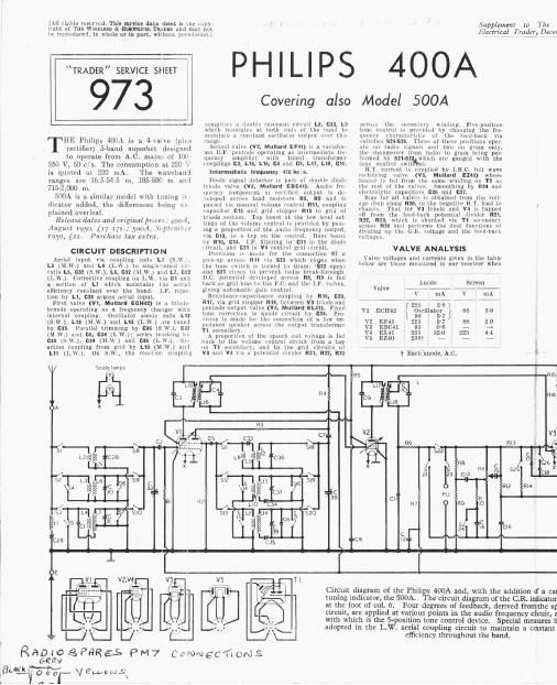
Circuit diagram of the Philips 400A and, with the addition if a can
tuning indicator, the 500A. . The circuit diagram of the (LR inlicator
_ Four degrees of feedback, derived fromthe 5;
Circuit, are applied at various points in the audio frequency cicuit, a
with which is the 5-posifion tone control device.
adopted in the LW. aerial coupling circuit to maintain a cclsrant

Special meaures l1

Page 2

in T11:

Winks: 57'

1L: 1319911117619: 193)

It was nperating on AC. mains U! 235 \.'1'lie
receiver was tuned to the highest wavelength
and of the M. W. blind With the volume control
aL mnximuni and the lune swiwh fully unti-
clockwise, but. mere was no signal input.

Voltage meagiirementa were mnile With mi
\\'0 llccbronic Tcstmetor. which introduces no
appreciable voltage drop in [he 1il'ciiit t0 nhlcll
ii is coiiuel'tcil, iullI :illnwiiill1 mliNL lie mall? fur
the load imposed by other mllei'» [he valiant?
measured across R2 was E .5 V Mid that on the
cathode of V5 was 260 \ All readings were
taken lh ilie negative llil'tFr leiiil i'llllliccted
to rhassis.

COMPONENTS AND VALUES

i
Values LOEil'

RESISTORS
mm.
111 vino. A .. 71.51111 H3 3
112 v1 cinch. 33km . G3
113 v1 onusmpmr . Am (:1
R4 One. 1131'. feed . 33m jGJ
115 5.1} Iced . 27km . 11
no 111. shipper . 47m 04
R7 A (1.1;. demnnllnl; 1 11m 1'.
fig }Signul diode lonil.. { 332$ Li
11.10 'rnne rmrccmr . <1st 11:;
Mi Volume cuniroi ., . 265310 F3
RI? \3 (LG. ... -» Z'ZMQ E1
R13 Grid stunner . 47k!) E3
R14 l Parttune annual 533g {2
R15 1 '
R16 1 3 "was 10 1 100m Fi
R17 V4 (in. . . seeks: r4
ms v4 grill stopper . ikn 14
R19 6.13, decoupling . 6 BM!) in
1120 Common (:15. .. 131m 134
fig; Neg. ised-bnchl 223%; f3 '
R23 puccuiial divider 5,wa E4
1124 111', smoothing 12m Cl

ion if a cathode ray
R. indicator is shown
from the speech coil
cy circuit, associated
measures have been
a constant coupling

\Iiluua Loca-

17 APACITORS


Acriul counllug
{7. 1+.

hill: I. .
tuning , .
\ 1 051. O. U . .
L. \\'. (N, [J'iilinil'l
05c iuiuile coupling
5.1;. uncoup.
trans.{

(Tans

2nd Ll".
tuning
1.1" in piss
decoupling
}Tone munpomninn

AF coupling
.uuuph'ng
}Parts lune r'nntml {

Tone correciur
A 1' tIcoulllinpz


ODOZZuF
G B by pass lDUuF
Tone correction U 0047ul
ILF. by-pusi 0 Digit:
1 - I H
H 1 smoothing .. 47MF
I l1 nicer tune 3001
S W. aerial il' lm . 50111?
M.\\' nnml mnl 25pF
icriai mm. ZspF
Luniml ., 4El2pF
tiacki'l , 125111?
. , mi . 575m?
L.\V. use. tracker 175p!"
S.W osc. Him 1 30pF
. mm. illlmuer inilF
L.w. oscidrimmer 30pF
Oscillator tuning 492171
' Electrolytic. 1 Variable. lrchM
Approx.

OTHER (UDIPON NTS
i

values Locar
(ohms) lions

1.1:ulwrcoll V 37c A2


l L1
1.2 1-15 A1
1.9 Aerinl coupling coils { 100 11 A1
L4 183-0 A2
L5 \ ery low A1
L6 Aerial tuning coilsil b-U Al
L7 200 U A2
La 2"- A2
L9 Oscillator reaction 0 A2
Liu mils . l . . 21; i 2
Pl . i
11 , . '1er aw i
W Osgilémr tuning { M H
11% 1"- 19%:
1a . ri. ~
[416 j} 1 I l "'3 591-, 6-8 H1:
L17 l} Pri. 6-8 1:2
L18 2 I "5 Sec, 5 a 1'2
L19 }Smecli coil 2 8
'11 Prluiary 7711-0 Gil
Secondary, total 11-: Gal
.{ Primary, total . 741)
H. T. 5131:. , total 1000 Di
{Heater nee. Very luw
Heat coll fuse . . - D2

DISMANTLING THE SET

Removing cnassiafiliemovc the four couuul
knobs (recessed grub screws) from the front
nl ihe cabinet, wiihdrnwing their fixing Bi'lEWn
completely;

unsoider the leads from the speech coil calls on
the speaker;

ullsnlller inn lead from the enruling ing .11 L116
left ham! rear milk of ciliixsls;

remove two wood screw with washers, securing
scale lamp holders to top corner: of sub-bnflle.
nnll release llrlw. wire from hum. carriage;

rimOVE four Chassis bolts (itll washers anll
lock washers) and Withdraw cllasms.

When replacing, check that with the gun; lit
minimum, the 1-ilr111r coincides with zero (Ill
the 0-200 scale. The Mark speaker lend sliuillil
be connected to the right blind speech coil mg.

when fitting the contml knobs. first all]? them
cm to their llpimlle, than inserh the grub
screw. The knob boss is not threaded: Lhe
thread is In the spindle, and the screw applies
pressure to the far side of the hoss.

Removing Sunken-Remove nut at top edne of

"-PHILI PS
400A

973

T he appearance of the Philips 400A,

which has a plastic cabinet. The

500A has a woodcn cabinet. The

inning indicator is located on the
right of the tuning scale.

iu'lkil, xuurillg speech ruil Lug [Ililirl mm in.
llithlllg imp, and two rcmallllug nuts llOlillllK
Him 01' :pcukel to sill: Dame.

GENERAL NOTES

liwunhes 731-510 are xiii, mu-band swm-Ilu
L'zlligill lll .MU rotary unltn lJlllLIllll llin Lililaala.
PM 1 .llr indicated ill iilll llllllel 'llil\~i: \le,
:lllll ~ll1MIi in denall in [he 1llAgr in col. 1
m ili'ml \illcra me;- are il' nn 21> mu liulll lliu
I'i.il 01 al iliicrbeil cllusrlri

lllL lulll' Iruluw Lllkln ghee lli1' ~ViiL1ll posh
inn. un- Llw three control settings, stalling
il'iilll Lliu lull) nnlncluikww nuslllnn oi ihu
in l/l linrlll. A ilznll illillriiiin 1min .illll C rimmi.

:mgszr .llr the ions annual and ladIu/gl'am
L'liiiigc-UVL' :Vllbtllefi, ganged m n single rotary
inlli lmn all: Lilo chasm, 11s puniiion in indicated
in Ii|lf thinnis photograph, and it is sliuwli ill
lln Ill n. liu lliugrnin in i-ul a uvuicnl.

'llicil ai'iiOll is shown ill illi lilblc llrlilW ll,
sinlrlnn iloln 1hr- iiilly illiticlm-kvr e position
Ul llir: colllrol lmnh imil lining in [10 ill mini
il » l rkvd uli the control knob. A dAEh lli
lili 1 . ilpin. aiiil B closed. loEILlnII» 1... and A
|lr)\'iiie tllrci. control settings [or radio and
positions 1 and :. iwo further pmilimls 14 gram.
'lle 1'Ilyll|gl.UVel' occurs nuioinniicnlly.

i21,SZB are the Q. M B. lnuiila awn/Chis,
Killiuiil ilh the \olumc 1'1')lltlill RH.

$1:an anns.-Thesu am lwu Philips lumps
will M. E. . bases and clear tubular ilulbi rabid
11. ii ' V, (LS A. Their Mlle number is 8028]) 00.

Exiarnal Speakerr'l'wo 'ch llli: provided
(it We rear of the clmnsi liir :i [11w impedance
[5 7 11) ennui speaker.

Fuse Fti'l'hls consists of ii wilrmctnl llllk
\vl mil in llurnlfllly hooked over two liuoks on the
in... transformer, llrlliiillg umn tuuuillar.
\Hmll the link melts, one ii! the hooks springs
all fly from the other. chluccmunla are made
null n tyre 011.100 9 run

Wire Tucker! llcle HIE xii Lrilnnieu 11ml
(1 ilkflfi Ul Lin: spulial Philips ire- wound type
from which wire may he removed but to which
it. must ll it, he ilddcd. Vi hen millistmz fihthc

asliori piice nf wire .shrilllil |nc «Inwly unwound
WlLll lill two on Llle output Ilietei If output
1- c continue until peak output in detected.
and 1111 oil spare wire. Il output. falls. replme
tl'lmnlrr W'iill :1 "PW one.

Model 500A.v This mndel in fitted in R Wmili-il


HT.
Circuit dia- W w
gram of Lhe r-nU
tuning iridi- '00) l
! cater in the 2'2 l
I 500A. R8 is
! divided into 29°53)
1 mo pans to Ti (man 2? IT-ll->
i provide a n9 ONT
l iappingpoint
l for the con- warm
l 1101 grid.
I
I l
l
l.