Philips 3750 service manual

This is the 2 pages manual for philips 3750 service manual.
Read or download the pdf for free. If you want to contribute, please mail your pdfs to info@audioservicemanuals.com.

Page: 1 / 2
left right
philips 3750 service manual

Extracted text from philips 3750 service manual (Ocr-read)


Page 1

May, 1935

"Sem'ce Engineer

Supplement to The Broadcaster

39

I lwc sw1rcn

l |

MAXNS l l

TONE CONTROL

TRIM

Isr O

BAND

PASS 111 E 5
3 L <
.1 at _l
a: {D &

BARRETTER

04M.


OSC COIL

151' BAND
6

Evc I
PASS @OR C22

Rl4
CIZ

C9 cm.

0 .11
o
0 PASS
Ocz TRIM
01; i1
oce
0124
c 0122 ;3
MWTRIM mwosc
0C1 TRIM
1m
p - s
52 esco'rroa

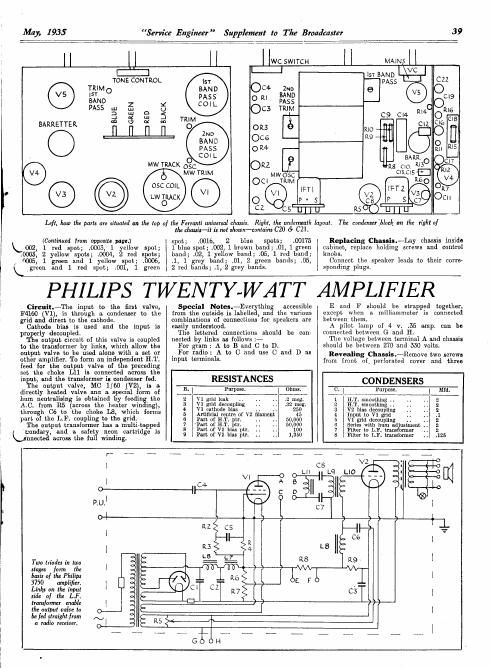
1.4!, how III: path are siluuled on the top of the Femmli universal chassis.

(Continued [ram opposite page.)

k002,1 red spot; 000,3 1 yellow spot;
0005, 2 yellow spots; .0004, 2 red spots;
0005: 1 green and 1 yellow 5 0t; .0006,

k green and 1 red spot; .00 , 1 green

the chaul's-t't' 1: no! shawn-canlax'ns C20 & C2].

spot; .,0016 2 blue spots; .00175
1 blue spot; .002, 1 brown band; .01, 1 green
band; W02 1 yellow band; .,05 1 red band;
.,1 1 grey band; .01,2 green bands; .05,
2 red bands; .1 2 grey bands.

Right, the underneath layout

The condenseflflack on the right of

Replacing Chassis.-Lay chassis inside
cabinet replace holding screws and control
knobs.

Connect the speaker leads to their corre-
sponding plugs.

PHILIPS TWENTY-WA TT

Circuit1.~'lhe input to the first valve,
F4160 is through a. condenser to the
grid an Vd1reet to the cathode

Cathode bias is used and the input is
pro rly decoupled

e output ci1cuit of this valve is coupled
to the transformer by links, which allow the
output Valve to be used alone with a set or
other amplifier. To form an independent H. '1.
feed for the output valve of the preceding
set the choke L11 is connected across the

Special Noles.-Eve thin accessible
from the outside is labell , an the various
combinatlons of connections for speakers are
easily understood.

The lettered connections should be con-
nected by links as follows. -

For gram: A to B and C to D.

For radio: A to C and use C and D as
input temminals.

AMPLIFIER

E and F should be strapped together,
except when a milliammeter is connected
between them.

A pilot lamp of 4 v. .35 amp.
connected between G and H

The voltage between terminal A and chassis
should be between 270 and 330 volts.

Revealing Chassis.-Remove two screws
from front of, perforated cover and three

can be

input, and the transformer-15 condenser fed. RESISTANCES

The output \alve, MC 1/60 (V2; is a R. Pur Ohm CONDENSERS
diiectly heated valve emu a. special orm of .___l pow l 3' _E;l Puma I md
hum neutralising is obtained by feedin the 2 \1'1 gnd leak .. .2 meg. 1 ILT smoothing 2
A. C. from R5 (aczoss the heater win ing), 72 3i 8130138ch11111; 1 3221:3131 a ngblsmfiothing. 2

an e 1113

through 05 t0 the 01101 1'3 WhICh 50" 5 Artificial centre of v2 inment 45 4 1111111350 51°31? .3
part of the L F. coupling to the glid. 6 run of HT. pt 1'. . 50,000 5 V1 grid decoupling 2

The output transformer has a multi topped a :12: 0§ iiéTt pt! 11 50.?33 3 fig gm: I{mm adjustment. 2

a o map. 1 L trasfor r 2
2113:? 1351;111:1523? $315803!!ng 5 9 ram of v2 1111111 pm 1,350 3 Filter :1: Ln. tuxnlsfoxggr .125
r- ____ _ ,fi _ __ g __ _ _

VI

Two Irioda in 1100

one

stage: farm the
basis of the Philip:
3750 mph :1.
Links on the input
side of the LP.
lmnrfonner enable
the output value to

I): led straight from

a radio receiver.

Page 2

40 Service Engineer Supplement to The Bmadtaster May, 1935
R8 I R9 12 R3

@ @

. FUSE
L)

OC

Ocz

OUTPUT
[E] TRANS3
smoomwe
CHOKES
L6£rL7
MAINS
TRANS? OHT+
FUSE

C30

The practical layout diagrams of the Philips 3750 PA. mnpii er.

(Continued [ram previous page.)
screws from the flange at each side of the
base and remove the four screws inside the
rubber supports.

General Notes-The voltages in this
amplifier are in the neighbourhood of 1,000
volts, and due care must be taken.

SSGIHJMV'J NOBN

@
C CDWGD

02: 90 K4»
(10.340
9.89 b
0:8
L H Duo
0.3

The wires are hunched, and to facilitate
the tracing of leads a continuity tester is an
advantage.

Replacing Coven-In replacing the
cover it is better to replace the bottom plate
and fix b the two screws underneath the
valve plat arm.

The remaining two screws should not be

J
J

inserted till after the perforated cover has
been replaced.

VALVE READINGS

Valve. Type. Electrode. Volts. ILA.
1 F 4/60 . . node -380 9.54.0.5
2 MC 1/60 . . anode 950-1050 48-52

GENERAL ELECTRIC
D.C. FIVE

Circuit. - The first detector oscillator
valve, DsB clear (V1), follows a band- ass
aerial coupling. As it is a screen-grid va ve,
reaction coupling is in the cathode lead, with
suppressor feed to the aerial coil.

Coupling to the next valve is by band-pass
I.F. transformer (frequency 107 km), and
the tuning condenser of the primary is used
as the H.F. feed to the anode reaction coil.

The LF. valve, VDS clear (V2), is fol-
lowed by a second band-pass I.F. transformer,
and volume is controlled by means of a poten-
tiometer, R21, which simultaneously damps
the aerial and increases the bias on V2.

A DSB clear second detector (V5) operates
as an anode~bend detector, and gramophonc
coupling is obtained from the low ELF.
potential end of the secondary of I.F.T.2 and
cathode through two isolating condensers.
The anode circuit consists of a resistance and
by-pass condenser LF. filter, a resistance
capacity L.F. coupling and anode decoupling.

A filter for double the intermediate ire»
quenc (214KC) is included in the anode cir-
cuit ( .7 038).

'Ihe output peutode, DPT (V4), is pro-
vided with tone control by a condenser in
series with a variable resistance between the
anode and chassis, and is tone compensated
by a condenser, on) across the extra speaker
sockets.

The extra speaker is filter fed between the
anode and cathode. As usual, the speaker
connections contain the meke-befote-bteak
swiwh for disconnecting the internal speaker.

Mains equipment consists of H.F. chokes
and smoothing chokes in each of the mains

leads, w h lie the
barretter lamp,
type 251, and the
speaker field are in
series w i t h the
v a l v e h e a. t e r
supply. Bot-h mains
leads are fused.

The valves are
16 v. .25 amp type.

Special Notes.
--The 0 flier oi liar A.V.C.5.
heater wiring is :
barretter, speaker field, V4, V1, V2 and
V3. The special modifications to the
circuit when used with the mdiogram are
also shown on the circuit diagram.

The dial lamps are the 3.5 v. .5 amp. type.
If this type does not have a satisfactory life
the 6.4 volt .4 amp. 12 mm. MES type may
be substituted. With the latter the illumina-
tion will not be so bright.

VALVE READINGS

No signal ; 200 and 250 volt mains.

Valve. T . Electrode. Volts. Mn.
ype 200 250 60
1 D513 (5) . anode 150 190 1 l
screen 55 75
2 vnsm anode 170210 a 9
screen .. 55 75
3 DSB(5) . anode 65 .335
screen 65 85
4 DPT(5) . anode .,145150 30 4o
aux. grid 170210 a 5

*Very high values ol'resismnces cause readings to
be entirely misleading.

a

The D.C.5 by the G.E.C.

is Wuivalent to the [tuni-

Quick Tesls.--Between the terminals on
the speaker transformer and chassis :_

Left hand (1) red and black, LS. field.

(2) Red. IiT. smoothed, 170 volts.

(3) Green and block, speech Call.

(4) Red and black, speech coil.

(5 Orange and black, speech coil.

(6 Orange, V4 anode, 145 volts.

(7) Gray, L.S. field

Removing Chassis.-Remove the knobs
by removing insulating composition from cen-
tral holding screws and remove screws.

In the table model remove the two wooden
battens underneath the cabinet, and then
remove the four holding screws. In the con-
sole and radiogram models the screws are
underneath the platforms.

General Noles.-In some models resist-
ances of 80 ohms each may he found connected
across the pilot lamp leads.

With the valves in. position and cold the
total resistance between the mains leads should
be approximately 600 ohms.

In the table and console models all the

(Continued an opposite page.)