Philips 372 b service manual

This is the 4 pages manual for philips 372 b service manual.
Read or download the pdf for free. If you want to contribute, please mail your pdfs to info@audioservicemanuals.com.

Page: 1 / 4
left right
philips 372 b service manual

Extracted text from philips 372 b service manual (Ocr-read)


Page 1

IIlllIlllIIllIlIllIlllIIIIlll IIIIIIIIIIIII I IIIIIII. ,

I1IIIIIII111III1I1I1III1IEII1I IIIIIII III: I1IIIIII

1 I.11l
TRADER" SERVICE SHEET

617

ilfllllllllllllnimll}11111111111111111 111111111111111111 1111111111113111111:1'1111'111111 1 11111111 1 11.11

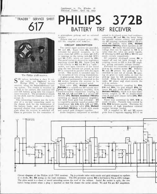
The Philips 3728 receiver.

IX Hikes, including :1 thus H mt
put who,
Philips 5721;

"or. using the Supcnnduct 1nce tun-

' tom The chassis 1s n1cunte1l 1111

a shelf in the cabinet, the combined HT

and GB buttery going into the compart-

mcnt beneath it. The accumulator stanis
on the shell, and the chassis is slmprd to
accept it.

Two inte ing features are the inclu-
sion of a 51 way connecting panel (In
the chassis deck ior the termination 3f
the battery leads, and a mechanically
operated shutter that covers the tunirg
scale when the TELCIVGI is switzhed oil,
There is provision for the connection of

PLAlE 11111

me employed in he
a Zband battery

Supplement to The Wirelm Cv
{Electrical Trademi/flpril25,7123}

PHILIPS 372B

BATTERY TRF RECEIVER

a gramophone pickup and an external
speaker.

Release date and original 111m. : 1934,-
Lll 115. complete wit/1 batteries.

CIRCUIT DESCRIPTIO N

Two aerial input s01 lots me pr'01idcd
A1 and A2. Input hum A2, which is
intended for general inception is Vin
seiies choke L1 (MW) or choke L2 (L '
to toppings 0n the tuning coils L3 (.\1 "1
and L4 (LVVI which are tuntd by 011.
The aerial circuit is shunted by impedance
matching circuit R1, 02. Input from A1
is fed directly to A1, but A1 is a split
socket, and upon insertion of the aerial
plug the two sections are joined, so that
c1 is connected in parallel with the input
circuit. This socket is intended only for
the reception of very strong transmisions.

A plate aerial, fitted in the roof of the
cabinet and permanently connected to the
A1 socket, permits the receiver to be
operated Without an external aerial.

First \al1c (V1 Mullnrd metallised

,PMIZM) is a 1111'izible mu RF tctrode open

ating as signal frequency amplifier, wiih

' tunodrsreondory transformer coupling hy

L5, L6, L1, L8 and 024 to a second RF
tetrode (V2, Muliam metallised PM12A)
operating as signal frequency amplifier,
but with fixed grid bias potential. V2
is coupled by another Luncdrsecondarv RF
transformer, L9, L11}, L11, L12 and 011,
to a diode detector valve (V3, Mullnrd
metallised FM1HL), a triodc with anode
and control grid strapped together.
Audio frequency component in rectified

output is developed across load resistance
comprising R1 and R8, the latter being
the manual volume control, and passed
via AF coupling rondenser G10 t0 CG of a
third RF tetrode valve (VI, Mulllrd
metallised PM12A), which operates as AF
amplifier. R1 limits the maximum signal
voltage that can be applied to V4 to a
value that, the valve can safely handle.
ll filtering: by 611 and 013 in VI CG and
anode circuits respectively

DC potential developed across R8 is
lapped off and fed back through 11 do
coupling circuit as GB to first RF amplir
tier, giving automatic volume control.

Provision for connection of gramophonc
pick-up by sockets across Rs. Switches
SE and SS permit the pick up to he
switched in and out of circuit 85 open
ing on gram t0 niutc radio, so that the
pick up may be left permanently cone
nected When the receiver is switched to
radio, S1 closes and short circuits the
pick up sockets.

Resistance capacity coupling by R13,
(:14 and R14, via grid stopper R15, be
tween V4 and triodc driver valve (V5,
Mullard PMZDX), which is in turn trans
former coupled by T1 to doublcrtriodc
class B pushrpull output valve (V6, iMul~
lard PMZB).

Fixed tone corrcction by 011, 018 in
anode circuits. Variable tone control by
613, R18 between anodes Provision for
connection of high impedance external
speaker between anodes.

HT is supplied to V1 and V2 screen
grids from a separate tapping HT-I-l on

R5

as its

)_
111 V3
1

gm en [26 117

7 r
l as

9 « 55
F g is) g 54 C" 56

Ear cu Eur C PH 57 R3

. r1 r 1
ll
1

Circuit diagram of the Philips 3721! TRF receiver.
as a diode, R7, R8 acting as the load resistance.
The plate aerial is a sheet 01 metal extending across the roof of the cabinet.

V3 is a (node valve with anode and grid strapped to operate
The DC potential across R8 is fed back to V: as AVC voltage.
Aerial AI socket is split, the two

halves being joined when a plug is inserted so that CI shunts the aerial circuit. V1 and V: are RF amplifiers.

Page 2

i

i Under-chassis view.
l The switch units
:~ are indicated here
E by numbers in cir
l cles and arrows,
l the arrows indicat-
E ing the directions
1 in which the units
l are viewed in the
i: diagrams in column
3 3 overleaf. A dia-
1 gram in column 5
l overleaf shows the
i

i

i

i

i

i

i

i

i

i

internal connec-

tions of the multiple

condenser unit seen

in the top left-hand
corner.

the HT battery, the rest of file Circuit
lleing supplied from a single HT+2 tap~
pingi (irrid hias potentials for V2, VII
and V5 are obtained from tappings on a
potential dividerJ comprising resistances
R19, R20, "11I which is connected across
the GB section of the HT battery.

VALVE A NALYSIS

Valve voltages and Currents given in
the table (col. 5) are those quoted in the
makers manual. They are average values
and are wherefore approximate. Variar
tions up to 20 per cent. will not neces4
sarily indicate a fault. The figures are
based on the assumption that the poten
tial at HT+1 is 60 V, that at HTOZ is
130 V, and that. the GB- potential is
~31 V.

Supple-mm w The Wireless or
ElectricaLTraderz April 31le9

\Vhen readings are lyeing taken, the re- .
reiver should he swunlmd to NW, the
volume Control should be at. maximum,
and there should be no signal input.

Volfiages should be measured on the
most suitable srale of a 1,000 ohms-per-
mit meter whose negative learl is con-
iieited to chassis.

i
l Anode .uiodi- .Somn Sc eni
} Valve Voltage i'iurimt Voltage (ilrlonti
i (V (V) limAi

v3 mnzA 52

isruenx 125

V 6 PMZB 1201 1-101

'l Eat ll anode.

;Hiu (I v;
¢Hi.i it
a
:.
EXT Ll/
Ti Ls' LTi n3 \
Y = (is .
H175
«a.
:cii
;s . ,7
r I r ,. , ..
[ ii.
[ m
I mi
Vqu

61

COMPONENTS AND VALUES

.. 4.444-4

l

W


RESISTANCES \iillirs

(uluusi

11. unit shunt :l2.u.iu

\l U resistance 1 000. mu

1,0170 (mu

1 vi .0 i] m

SC: 5 decoupling .10 Ill

anodes decoupling Loon

. diode lDflIl :X'Zlml'llr
Manual anllml- i-nninll ,

purl. V3 dlilde lurid. SUDAN

Vt (G resistance ..

\2 V4 SGs and V4

Amide. HT fin-ii patell-
ll: ll divider . .

25mm
5 .0!!!)

on
v l anode load . . i 12.3 we
is i (} resistance 1, Oil!) 04m
V J grid skipper . . .. l 100 «mu
'1'! wiiuudnry shunt rosiiir- 10.0w
ances .. 10.000
Variable tone control ' 50,1100
GB batter ntentiul i 4.
divider y l) $33
CONDENSEES . \(alpfa
. u i
A1 aerial shunt 002.")
A2 Mrlfll shunt 0-00008
V 1 CG condenser 0-00001
V1 00 decoupling U 1
V '2 CG uondenanr 0 000025
V 1 V2 SG's decoupling U 5
i 11 V2 anodes decoup- { 0'1
[204
Caupiiug to V3 diode i u~uuuula
AF coupling to \ l U 01
li by pass .. l 0-0002!-
V 4 st} demupliui'g a 1
I ll by-pass . [1- 00025
V 4 to V 5 coupling D 01
HT circuit few of: . (l-l
Imx-iiriabie bone control out
I ixed tone Cori-caters { 833::
.l urial cirC. LW trimmer (i-mlunz.
AerinlciroJilWLrimmer l (mouozr
Aerial Circuit tuning . . (10013
1% mRF trans. LW crime 1
i) 0000"7

1st RF trans. MW trini-
we r
1th RF trans. SEC tuning 0-00013
2 id RF trans. LVV tliln~
mar 0-000027
2 id RF trans. MW ulmr l
0 000027

UOUUU27

2 Id RF dim. se'c'. tunii'g' 000043

1 Variable. 3 Ere-set.

PHILIPS
372B