Philips 229 b service manual

This is the 1 pages manual for philips 229 b service manual.
Read or download the pdf for free. If you want to contribute, please mail your pdfs to info@audioservicemanuals.com.

Page: 1 / 1
left
philips 229 b service manual

Extracted text from philips 229 b service manual (Ocr-read)


Page 1

PHILIPS
229B

Faur-valve, twa dr y battery portable superhet. Separ-
ate H T and LT batteries are
employed and provision is made for
an external aerial and earth.
Marketed I940 by Philip: Lamps,
Ltr/., Service Department, 79/94,
Cherry Orchard Road, Croydon,
Surrey.

lHE internal frame aerials. L2 (MW)
L3 (LW) are tuned by VCl and
connect direct to the control grid of the
heptode frequency changer valve VI. A
coupling winding L] on the frame aerial
assembly connects to the aerial socket.
The screen of V1 is fed from the HT line
via R2 decoupled by C3.
The oscillator section employs a tuned

grid circuit in which L4 (MW) and L5
(LW) are tuned by VCZ section of the
gang condenser. The grid leak is R3
and the grid condenser C41 The oscillator
anode reaction coils L6 (MW) and L7
(LW) connect via R4 to the HT line.

The IF output from V1 is transferred by
the IF transforrnercomprising L8, L9 to the
grid ofthe 1F amplifying pentode valve V2.
The IF transformers have adjustable
iron dust cores for trimming. A second
IF transformer L10, L11, couples V2 to
the single diode triode valve V3. The
diode is fed from a tappingon L11 and the
LF signal is developed across the volume
control R10 across which is the IF by-pass
condenser C18.

A potential divider network R8, R9,
is connected across R10. and from a
tapping on this network AVC is applied
to V1 and V2 via decoupling components
RS, C2 and C11.

From the volume control R10 the LF
signal is coupled via C19 to the grid
circuit of V3 via filter network R11, R12,
R13, C201

Resistance capacity coupling via R14,

C22 and R15 is employed to couple» V3
to the pentode output valve V4. A grid
stopper R16 is included in the grid circuit
which is returned via the automatic bias
resistance R1 (decoupled by C1) to the
LT negative line.

The output transformer L12. L13,
couples V4 to the low impedance loud-
speaker L14. C23 provides a permanent
degree of tone correction.

GANomo

IF Circuits-Remove control grid top
cap connector of V1 and connect a
5,000-ohm resistance between the control
grid and the AVC line. Switch to MW and
tune receiver to the bottom end of the
MW band. With volume control at maxi~
mum, inject a 470-kc signal via a .032 condenser to the grid ofVl.

Detune the primary or secondary
circuits by connecting a 10,000-ohm
resistance in series with a .1 mid con-
denser between chassis and the anode or
grid end of the coil and trim for maximum
output as follows :--

Detune L10 and trim L11. Detune

JULY, 1943

VCE

VCI

$23.
@
@0@@

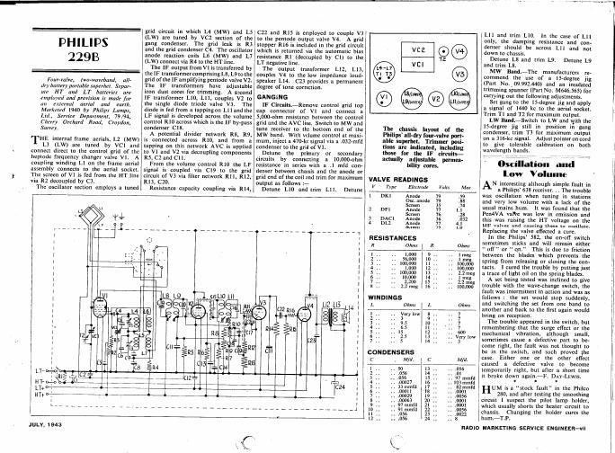
The chassis layout of the
Philips all-dry four-valve port-
able superhct. Trimmer posi-
tions are indicated, including
those for the IF circuits-
actually adjustable permea-

bility cores.
VALVE READINGS
V Type Electrode Vans
1 DKl Anode 79
Osc. anode 79
Screen 35
2 DH Anode 71
Screen 76
3 DACI Anode 36
4 131.2 Anode 77
Screen 79
RESISTANCES
R Ohm R
1 1
2 .
3 .
4 1
s 11
6
7 ..
x 1.
WINDINGS
L Ohms L
1 .. Very low 8 .
2 .1 3 9 .
3 11 915 10 . .
4 1. 6,5 11 1
s .1 15 12 1
6 1. 2.5 13 4
7 ., 5 14 .
CONDENSERS
c , Mfd. C
1 .. so 13 1
2 .056 14 ..
3 1. .056 15 .1
4 11 .00027 15 ..
5 1. 33mm1d 17 ,.
6 1. . .00011 18 ,1
7 1. 1 100029 19 1
8 1 1 100063 20 .
9 . 97 mmfd 21 1
11) 1. 91 mmfd 22 .
11 . .056 23 1
12 . .056 2-1 ,

Lll and trim L10.

1n the case of LI]
only, the damping resistance and con-
denser should be across L11 and not
down to chassis

Detune L8 and trim L9. Detune L9
and trim L8.

MW Band.iThe manufacturers re-
commend the use of a 15-degree jig
(Part No.09.992.440) and an insulated
trimming spanner (Part No. M6465) for
carrying out the following adjustments.

Set gang to the lS-degree jig and apply
a signal of 1440 kc to the aerial socket.
Trim T1 and T2 for maximum output.

LW Bani-Switch to LW and with the
lS-degree jig still in position in gang
condenser, trim T3 for maximum output
on a 316-kc signal. Adjust pointer on cord
to give tolerable calibration on both
wavelength bands.

03c entity}: and
low Volume

AN interesting although simple fault in
a Philips 638 receiver. 1 . The trouble
was oscillation when tuning in stations
and very low volume with a lack of the
usual mains hum. It was found that the
Pen4VA vaflte was low in emission and
this was raising the HT voltage on the
HF valves and causing these to oscillate
Replacing the valve efl'ected a cure.

In the Philips 582, the on-ofi" switch
sometimes sticks and will remain either
off or on." This is due to friction
between the blades which prevents the
spring from releasing or closing the con-
tacts. I cured the trouble by putting just
a trace of light oil on the spring blades.

A set being tested was inclined to give
trouble with the wave-change switch, the
fault was intermittent in action and was as
follows : the set would stop suddenly.
and switching the set from one band to
another and back to the first again would
bring on reception

The trouble appeared in the switch, but
remembering that the surge effect or the
mechanical vibration, although small.
sometimes cause a defective part to be-
come right, the fault was not. thought to
be in the switch, and such proved the
case. Either one or the other effect
caused a defective valve to become
temporarily right, but after a short time
it broke down again-F. DAY-LEWIS.

1 t .

UM is a stock fault" in the Philco
280, and after testing the smoothing
circuit I suspect the pilot lamp holder,
which usually shorts the heater circuit to
chassis. Changing the holder cures the
hum.-T.P.

RADIO MARKETING SERVICE ENGINEER-VII