Philips 229 b service manual 1

This is the 4 pages manual for philips 229 b service manual 1.
Read or download the pdf for free. If you want to contribute, please mail your pdfs to info@audioservicemanuals.com.

Page: 1 / 4
left right
philips 229 b service manual 1

Extracted text from philips 229 b service manual 1 (Ocr-read)


Page 1

IIIIIIIIIIIIIIIIIIIIII IIIIIIIIIIIIIII I . III I IIIIII I I I IIIIIIIIII IIII'I I IIIIIIII IIIII IIIIIIIIIIIIIIIIiIInlIIIIIIIIIIIIIIIIII IIIIIHIIII IIII

TRADER " SERVICE SHEET

504

IiIIIIIIIIIIIIIIIIIIIIIIIIIIII'IIIIVIII IItI IIIIIIIIMIIIH I IIiiIIIIi I I IIIIIIIIIIIIIIIII'I IIIIIIIIIIIIII'IIIIIII] IIIIlEl llIII EIIII III I" I

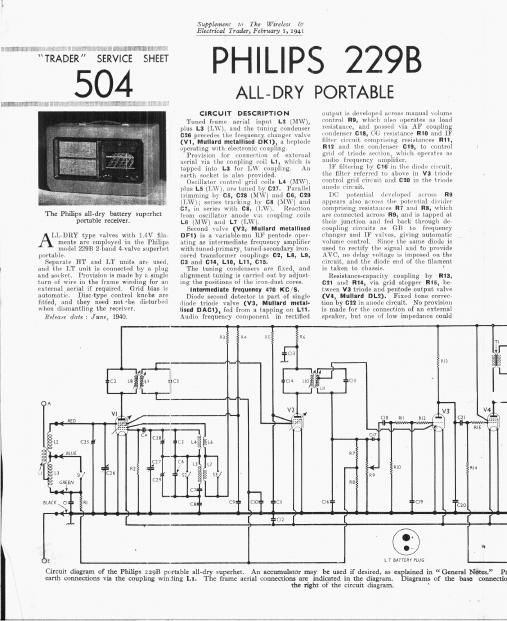
The Philips all-dry battery supcrhct
portable receiver.

LLDRY type valves with 1.4V filnr
monts arc cmploycd in the Philips
model 22913 2 band drvalvc superhct

portnhlc.

Soparutc HT und LT units (in used.
and tho LT unit is connootcd by a plug
rind sorkot, Provision is made by z. singlc
turn of wire in the frame winding for an
cxternul ucrinl if required. Grid bias i.»
automatic. Discrtype control knobs are
fitted, and they need not -be disturbed
when dismantling the receiver.

Heleum date: June, 1940.

Supplemcm In The Wireless d:
Qctriml T123131, 5917114311141, 1941

PHILIPS 229B

ALL- DRY

CIRCUIT DESCRIPTION

Tuned frame aerial input L2 (MW),
plus L3 (LW). and the tuning condenser
026 procedos the frvqucncy chnngrr valve
(VIl Mullard metallised DK1), n Iicptode
operating with electronic coupling.

Prm ion for connection of external
aerial \ia the coupling mil L1, which is
tapped into L3 for LW coupling. An
earth socket is also provided.

Oscillator control grid coils LII (MW).
plus L5 (L\\'}. are tuned lxy 021. Parallel
trimming by CS, 028 (MW) and 66, 029
(LW): series trucking by 08 (MW) and
G1. in series with cs, ILWJ. Reaction
Ironi oscillator anonlc no coupling coils
LS (MW) and L1 (TAV).

Second vnlvo (V2, Mullard matallised
DF1) is a variahlcrinu RF pcntode open
sting as intermediate frequency amplifier
with tunedprimary, tuncdrsecondziry iron
cored transformer couplings 02, L8, L9,
03 and cm, L10, L11, ms.

The tuning condcuscrs are fixed, and
alignment tuning is carried out by adjust
ing the positions of the ironrdust coresi

Intermedilte lrequency 41o Kc/S.

Diode second detector is part of singln
Iliuclc triorlc valve (V3, Mullnrd mettl-
Iised DAG1), fed from a tapping on L11.
Audio frequency C(nnponcnt in rectified

PORTABLE

output is dcvclopcd ur'i'oss manual \oliimc
control R9, which nl operates as loud
iPSlSitnlcc, and p \'in AF coupling
(IllClCIlflFl' C18, CG stance RIO and IF
filter cirnnt comprising resistances R11,
R12 and the condenser 019, to control
grid of triode sortion, lilt'll opci'otcs (H
nullio frequency :iinpliilcri

lF filtering 11V C16 in the diode circuit.
the filter refer d to above in V3 trimlo
control grid circuit and 020 in the trimle
unodc circuit-i

DC potential IIb\tItlpPil ali'oss R9
appears also across the potential (Inidrl'
comprising resistances R1 and us, which
we connected across R9, and is tapped at
their junction and fed back through de-
coupling circuits as GB to frequency
changer and IF rulv , diving autoniuti
volume control. Sine. the same diode
used to rectify the signal and to provu e
AVC no delay voltage is imposed on the
(innit and the diode and of the filament
is taken to chat.

Itesistancocapacity coupling by R13,
Gil and R14, via. grid stopper R15, be
(wcen V3 triode and peiitode output valve
(V4, Mullard DL2). Fixed tone correcV
tion by 022 in anode circuit. No provision
is made for the connection oi an external
speaker. but one of low impedance could

R3 R4 R5 Rs
[1,103
CI4 LIO ==C5
LII
Cle RvI
CI7
R7
RIO
R9
REI
05::
I

0E

L T BATTERY Hus

Circuit diager of the Philips 2298 portable all- ~dry superhet
earth connections via the coupling winding Ll.

the right of the circuit diagram.

An accumulatoi- may be used if desired, as explained in General Notes. Pi
Thc frame aerial connections are indicated in the diagram. Diagrams of the base cunnecu'o

Page 2

1m Connected across tho speech coil tags
of the internal speaker.

Grid bins potential for V4 is obtained
initolnlltioully from drop along H18 in the
negative HT load to Chassis. This auto-
matic (11'; eil-I'uit is bypassed by an elec-
trolytic condenser 014, while a second
electrolytic condenser 013 forms an HT
roservmr.

COMPONENTS AND VALUES

llilt liVV trill-kw
Cd User 0' uit li[\V trclrkor
(:9 v1 so decoupling
(-10 v2 00 decoupling
011 V2 SG decoupling
012 IT circuit 1w by s
013 v2 anode (humming . u
on }2ml IF transformer tuning { 3000097

0 001 mm
0

CONDENsnm Viiluw

um)

ll 1 v1 11( minim i; llrlrluplimz 01m

02 lst 1r transforuivr tunlng{ 0 "00097 ,
(33 condensers ,1 U 00000]
(74 v1 050. Cu condemn-r 0 00027

as 0-10 rii'r, \{W il\t'1l tiim-

0 00003 i

(36 Use. cire. LW maul tlinr l

000012

l

C15 condenser); 000103
C16 IF by- mass , 0-0001
(117 Tone, compensator l 000087
018 Al" coupling to V3 triodc 0 0056
(119 Pa rt iii flltri firruit l (l 0001
:20 W by. s 0 0001
('21 \i 'i triodo 5m V4 Al" coup-

ling .. 0 0056
(22 Fixnd tone 001' film 00022
{23 HT ClICUlt reservoir 8'0
(124 V4 (lB circuit by-piiss . 50- 0

l (725: MW frame aerial trimmer 0 00003
i (1261' Frame Mi'ifll tuning . 0- 00049
(271 Oscillator circuit tuning 0- 00040
i UZS 050. circuit MW trimmer 0-00003
029, Osci circuit LVV trimmer 0-0000?)

Eli-ctrolytin. 1 Variable. Pre-Sct.

§0-000276;LAF and 0'000015uF in parallel.

n HT?
BLUE 7

(27 [

:=c22
GREEN \

f I 74 I

I 7 in
W is ={c74

5e ,

f H T

Notes. Provision is made for external aerial and

15 connections of the four valves are shown on

Supplcnmzl in The Wirelcsl 13"
Electrical Trader, February I, 1941

229 B

Under-chassis view, The connections of ihe frame aerial leads can be gauged
approximately, while the colours marked aggrce with those in the circuit diagrami

RESISTANCES Values
(ohms) l
in \ 1 antmlI- CG decoupling 100,000 ,
, R2 \ 1 050. u; resistancr .. 100,000
Rf} - v 1 an anode TIT feed 1,000
, R4 , v 1 so HT feed . 56,000
R5 l2 so in: feed . . 10,000
R6 V. 9 node HT food 9 2,200
i}; 1 }AV c feed pnbentlal divnl §v5g3rggg
M l Manual volume control' l
v3 diodn load mismncc 1 000 ,000
R10 v3 triode (JG rcsismnoe ,,200,ooo l
11%}; }Parts of H mm circuit 334%
R13 V 3 triode anode lead 10003000 ,
n14 V4 CG mum-ice . , 2,200,000
1115 v4 grid stopper \ 100,000
B16 v4 GB resistance.. 1,000
Approxl
OTHER COMI-ONENTS Values
(Chum)

£3 }Friune :lEIl'll uimlingn
L4 080. cm. MW timing (0
L5 03c. cile L tuning ('(Ill
Le Osrillatnr Mw function
ii; Oscillat/lr l.\v ieliiquuii

v . 1']
L9 }lst H mm Sm


fl? }2inl 1r «inn 1;

L12 Speaker speech no
T1 Output trans {1 8

will"

31-33 , Wiivebanrl iuiiclias'
S4 IT circuit switch ganged 7
l as l in circuit switch 1w

VALVE ANALYSIS

Valve voltages and rulrmils given in
ihu illlllC (ml. 6) are those measurvd in
nu: receiver when it was operaling with :i
new HT battery reading 90V on load.

The receiver was tuned to the lowest
wavelength on the medium we've hand
ind the volume mntrol was at maximum.
but the frame aerial leads were disconr
named and connected togethr-r, so that
there was no signal input.

Voltages were lnuauuud in, the 400 V
in of 11 model 7 Universal Avonlcler,
limos heing negative

Anode Anoili- Sen-on 1 Screen
Val (- Vultlige Current Voltage Curront
(\ ) (mA) (V) (111A)

015
V1 DKI {82 Osciljlulor } 30 0-74
79 l 1-0
\ 2 HF] 77 l L4 76 035
V3 DACI 14 0-04 # -
V4 :12 80 3-13 52 0- 7

DISMANTLING THE SET

Removing churn-Remove the smaller
lizllwhte est-iliilleun whiLh snrmunlln
(he tuning 51 .ilu (four LUlliliLl sunk
lltfrtll :crews. one in each Lulllm at ll'ullt
ul' it carrying case);

linslilth-z the three leads llum the frami-
aerial titgs' on the hinged flap forming
the back uni-r of the can uml one
load rum the earth sul'ktt

vlnuvt- uni (leat lililtling these leads to
the buttum of the cane (um- round-head
00d m-i-ewp;

illsolde froln the speaker transiul-lllor
the halls connecting it Lo the i-llussis;

wume the [our L'llvoso-heud screws holdr
lug tic ('li' $15 to the bottom Ui the
Flue.

[VI/u: whining, tunnel-t the Sal'lt-elilfll
npuakur lead to the left-ham! tag at the
IBaH' if the speaker translurlnur, and
the screening strip to the leitrhzmd
tag a, the front;

mimect the plain yellow lead to the right-
hund tag at the rear of the transformer.

Ir-mmct the frame aerial leads as follows,
\ lowing the receiver from the rear, with
the h ngetl flap lying flat, and number
mg tie (our tags on it from left to
right :

. red;

ill blue

ll. no external connection;

, greet.

50 FHILIPS 1