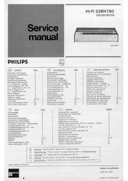
Philips 22 rh 790 service manual

This is the 31 pages manual for philips 22 rh 790 service manual.
Read or download the pdf for free. If you want to contribute, please mail your pdfs to info@audioservicemanuals.com.

Page: 1 / 31
left right
philips 22 rh 790 service manual

Extracted text from philips 22 rh 790 service manual (Ocr-read)


Page 1

HFFi22RH790
00/22/30/33

TRASBOZ
PHILIPS '°
Contents Page ® Inhoudsgpgave Pag. ® Table des matiéres Pig
Functions of the lambs 1 Knopfunkties 1 Function des boutons 1
Connection possibilities 2 Aansluitmogelijkhednn 2 Passibiiités de raccordement 2
Specification 2 Specificatie 2 Spécifications 2
Voltages measured 2 Gemeten apanningen 2 Tensions mesurées 2
Electrical adjustments 2 Elektrische instellingen 2 Réglages électriques 2
Mechanical adjustments 2 Mechanisehe instellingen 2 Réglages mécaniques 2
P.c. board top + wiring 3 Print bovenzijde + bedrading 3 Dessus platine + cablage 3
Circuit diagram HF + IF 4 Principeschema HF + MF 4 Schema de principe RF + F1 4
P.c. board bottom HF + IF 5 Print ondetzijde HF MP 5 Dessous platine RF + F1 5
Circuit ding-ram LP 6 Principeschema LF 6 Schéma de principe BF 6
P.c. board bottom LF 7 Print onderzijde LF 7 Dessous piatine BF 7
Block diagram 8 Blokschema 8 Schema synoptique 3
Diagram description 9 Schemabeschrijving 9 Description du schema 9
Hints for repair 9 Reperatiewenken 9 Conseils en cas de reparation 9
Adjusting instruction 10/11 Afregelvoorschrift 10/11 Instructions de réajustement 10/11
Cord path 11 Snarenloop 11 Mouvement des courroies 11
List of mechanical parts 12 Mechanische stuklijst 12 Nomenclature mécnnique 12
List of electrical parts 13 Eiektrische atuklijst 13 Nomenclature électrique 13
® Inhalt Seite Q) congene pgi a
Bedienlmlfipfe 1 Funzioni delle manopOle 1
Ansehllisse l Possibilita di collegamento 2
Spezification 2 Caratteristiche 2
Gemessene Spannungen 2 Tensioni misurate 2
Elektrische Einstellungen 2 Regolazioni elettricne 2
Mechanische Einstellungen 2 Regolazioni meccaniche 2
Printplatte Oberseite + Verdrahtung 3 Disegno della piastra del circuito stampato 4» filatura 3
Prinzipschaltbild HF + ZF 4 Circuito eiettrico AF + F1 4
Printplattenunterseite HP 4» ZF 5 Late inferiore circuito stampato AF + F1 5
PrinzipschaltblId NF 6 Circuito eletnico BF 6
Printplattenunterseite NF 7 Late inferiore circuito stampato BF 7
Biockschaltbild 8 Schema ablocchi 8
Schaltbildbeschreibung 9 Descrizione del circuiw 9
Reparaturhinweise 9 Metodo di riparazione 9
Abgleich 10/11 istruzioni per la regolazione 10/11
Seillauf 11 Disegno della cordina 11
Liste mechanischer Teile 12 Elenco companenti meccanici 12
Liste elektrischer Teile 13 Elenco componenti elettrici 13

9®®®9

Warning: "Touch control" has a 300 V supply voltage!

Wearschuwing: "Touch control" is uitgevoerd met 300 V voedingsspanning'.
Attentions: Le "Touch control" est alimenté a 300 V!

Achtung: "Touch control" ist mit 300 V Speisespannung ausgefuhrt!
Avvertimentoz il taste di controlio ha una tension: di aliuientazione di 300 V'.

Index: C524711-CS24723

SERVICE

Subject to modlflcatlon

4822 725 10497

Printed in the Netherlands