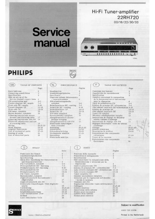
Philips 22 rh 720 service manual

This is the 30 pages manual for philips 22 rh 720 service manual.
Read or download the pdf for free. If you want to contribute, please mail your pdfs to info@audioservicemanuals.com.

Page: 1 / 30
left right
philips 22 rh 720 service manual

Extracted text from philips 22 rh 720 service manual (Ocr-read)


Page 1

Hi-Fi Tuner-amplifier
22RH 720

00/16/22/30/33

1726A
PHILIPS m
TABLE OF CONTENTS ® INHOUDSOPGAVE ® TABLE DES MATIERES
Page Pagina Page
Knob functions 2 Knopfuncties 2 l-onctiona des boutons 2
Connecting possibilities Ii Aansluitmogelijkheden :t Possibilités de raccordemem 3
Specifications 3 Specificatie 3 Specification 8
Data on set-up of the Gegevens opbouw dokumentatic Données concernant la composition
Service Manual vrepair hints 4 1 reparatiewenken 4 do Ia documentation at instructions
FM preselection unit 5-6 PM preselectiegedeelte pour la réparation 4
Circuit diagram HF +supply 7-8 compleet 5-6 Unité de présélection FM 5-6
Prim. side HF +supp1y 9-10 Principeschema HF weeding 7-5 Schema dc principe HF +alimentstion 7-8
'Circuit diagram LF - 11-12 Printzijde HF *voeding 9-10 Cbté platine imprimee Hleimentntion 9-10
Print side LF 13-14 Principeschema L? 11-12 Schéma de principe BF 11-12
FM tuner. complete 15 Printzijde LF 13-14 cm platine imprimée BF 13-14
Stereo decoder. complete 16 FM tuner compleet 15 Tuner FM complet 15
Adjusting instructions stereo Sicrco-dckoder compleet 15 Décodeur stéréophonique complet 16
decoder and trimming table 17 Afregelvoorschrift stereo- instructions de raglage du décodeur
Adjusting instructions AM-Fiii 18 decoder trimplan l7 stéréo +tnblenu d'njustage 17-
Electrical adjustments and test Afrcgelvocrschrifi AM-FM 18 Instructions de réglage AM-FM 18 R [Q .
of trimming table 19 Elektrische instellingen Réglages électriques Hexte du tableau (4
Wiring 20.21 .22 tekst trimlabel d'ajustage 19 5
Block diagram 23-24 Bedrading Cablage 20 can \|
Diagram description 2526 Blokschema Schema synoptique 23-24 . \
List of mechanical parts 21-29 Schemabeschrijving Description du schéma 25-26 \,\
Routing oi cords 28 Mechanische stuidijst Nomenclature des composants
List of electrical parts :30 Snarenloop mécaniques 27-29 [ \E
Elektrische stuklijst Trajet de la courroie 23 f
Nomenclature des composants
électriques 30
® mHALT
Seite Payne
Mtionen der Knbpfe 2 Funzione delle manopole 2
Anscltlussmbglichkeitcn 3 Possibilita di collegamento 3
Spezifizierung 3 Specificazioni 3
Duten (thei- Anordnung der Dokumentation Dali concernenti Ia composizione della
und Reparaturhinweise 4 documentazione e istruzioni per la
IM-Vorwahlteii. komplett 5.6 riparazione «i
Prinzipschaltbild HP 1 Speisung 7-8 Unita di preselezione FM 5-6
Printplattenseite HF ~Speisung 9-10 Schema di principio HF w alimentnzionc 7-8
Prinzipschaltbild NF 11-12 [am circuito ammpato HF +alimentnzionc 11-12
Printplattenseite NF 13- 14 Late circuito stampato BE 13- 14
Flu-Tuner, komplctt 15 Tuner complete FM 15
Stereodecoder. komplett 16 Decoder stereoi'onico completo 16
Abgleichvorschrift Stereodeooder + lstruzioni per le regolnzioni sul decoder
Abgleichplan 17 » tavola di taraturn 17
Abgleichvorschrift AM- FM 18 Tarature AM- FM 18
Elektrische Einstellungen +Text Abgleich~ Regoiazioni elettriche +tasto delle tarature 19
tabelle 19 Cablaggio 20.21.22
Verdrahtung 20 .21 22 Schema sinottico 23-24
Blackschaltbild 23-24 Descrizione dello schema 25-28
Sclnltbildbeschreibung 25-26 Elenco pezzi meccanici 27-29
Liste mechamscher Ieile z'l-zs schema delta cordina 25
Seillaui 28 Elenco pezzi elettrici 30
Liste elcktrischer Teile 30
Subject to modification
SERVICE 4822 725 10896
index: cssa743-csas7s7 Prlmed In "to NotMfl-ndl

,- _._'_