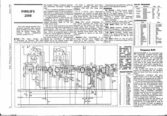
Philips 218 b schematic

This is the 1 pages manual for philips 218 b schematic.
Read or download the pdf for free. If you want to contribute, please mail your pdfs to info@audioservicemanuals.com.

Page: 1 / 1
left
philips 218 b schematic

Extracted text from philips 218 b schematic (Ocr-read)


Page 1

August, 1941

Radio Marketing Service Engineer

iDHILIPS
2l8B

Five-volts, battery-operated, three
wavebaml superhet with separate
Mode oscillator and Q.P.P. output.
Made by Philips Lamps, Ltd,
Century Home, Shafteabury
Avenue, Lomion, W.C.2.

circuit-The input circuits are
band-pass on medium and long
waves and transformer on short waves.

The familiar Philips combined capacity
and inductance band-pass coupling is
used.

V1 is a combined amplifier and mixer,
and a separate triode, V2 is the oscillator.
This used in a tuned anode arrangement
and the generated frequency is injected
to V1 via 013 and a screen grid.

Coupling between V1 and V3, the LF.
amplifier is by a trimmer-tuned LF.
transformer, and a similar coupling with
tapped secondary leads to V4, the
double-diode triode.

The A.V.C. diode is fed from the anode
of V3 and the load, R19 is returned to a
potentiometer, R2 and R3, between
H.T. negative and LT. positive, for delay
bin . A.V.C. is connected back to both
V3 and V1, being applied on all bands.

The R2-R3 point is also used to bias
the triode section of V3. Demodulated
signals are introduced by 029 and
tapped off by the volume control R24,
which is also the signal diode load.

V4 feeds a push-pull inter-valve
transformer through resistance and
capacity, R22 and 031 being tone
modifiers.

V5 is a Q.P.P. valve. Harmonic
suppressors are included in each grid,
and bias is obtained from the full voltage
drop across R2-R3. The output trans-
former has tone condensers across the
centre-tapped primary.

OWL-The switch indications in
the circuit represent the actual con-
struction of the wafers, the dots and
circles being fixed 'contacts, and the
radial lines the moving contacts. When
arcs are attached to the radial lines these
are shorting pieces which also move.
The diagram is shown in the S.W.
position.

Hamlet-The accumulator is a
2v. type, and the valve voltages are
given for a 120v. battery. There are
only four battery connections.

Connections are provided for a pick-up
and for a low~impedanoe speaker.
GANGING

1.1". Circuits-With receiver tuned
to bottom of the L.W. band, inject
128 kc. via small capacity to V1 grid.
Adjust T1 and T2 for maximum.

Connect a 10,000 ohm resistance
across I.F.I. primary, and adjust T3.
Remove resistance.

Connect 10,000 in series with .1 mfd.
across I.F.1 secondary, and adjust T4.

S.W1 Bench-There are no adjust»
ments.

M.W. Band-Connect 10,000 ohms
across I.F.1 secondary. Inject 1,442 km,
tune to 203 m. and adjust T5, T6 and T7.

L.W. Bani-Connect 10,000 ohms
across L.W. anode oscillator coil, tune
receiver and oscillator to 396 kc. and
adjust T8.

LF. Finch-Tune to top of L.W.,
inject 128 kc. to aerial and adjust T9 for
mmirnurn.


_H""l An

Interesting
characteristic of
this receiver is
the use :3 as
separate 0 e
as oscillator.
otherwise the set
iollows usual

mains superhet
lines with a
Q.P.P. output
valve replacing

the pentode. The
LP. transiormsr
is parallel led.

RESISTANCES
Ohm.

period .

VALVE READINGS

1' Tm Electrode Volts Ma.
1 vne Anode no is
Screen 32.6 .42
2 PMIHL Anode 45 1.4
Anolle(S.W.) M 2
3 VP2B Anode 104 1.32
Screen 35.5 as
4 rpm Anode 70 .85
3 orzze Anodes no 2
Screens 111 .55
CONDENSERS
c M/dt. c M/da.

Frequency Drift

ADIOGRAMS of one particular ty
repeatedly required service ca .
Each time the report was I.F.s badly
out of adjustment. On investigating
the cause it was found that the LE.
trimmers on top of the LF. cans came
very close to the gram motor and this
became very warm after running for a
considerable time, thus causing warping
of the trimmers.
The trouble was cured. to a great
extent. by adjusting the LR trimmers
after the gmm had been running for a

Temperature variations still gaVe
slight trouble. due to the bad design of
this receiver, but running the set with its
back of made a further improvement.

It may be mentioned that the oscillator
circuit is the one which generally causes
most trouble due to temperature varia-
tions. In some U.S.A. commercial
receivers temperature-com nsation is
carried out by shunting t e oscillator
trimmer with a bimetallic condenser.
Another method is to use two trimmers in
parallel, one having a negative tem-
perature coefficient, while the other has a
positive temperature coefficient.

In installing radio sets the efi'ects of
temperature should be considered. Put-
ting the set on ahigh shelf or with its
back to a window or flush up against a
wall should be avoided-Acres» Ross,
London, N4.