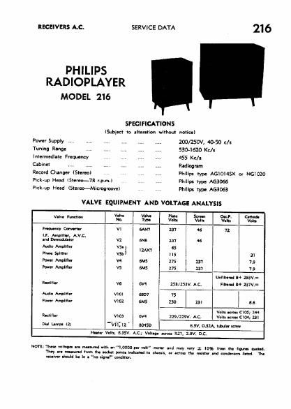
Philips 216 service manual

This is the 6 pages manual for philips 216 service manual.
Read or download the pdf for free. If you want to contribute, please mail your pdfs to info@audioservicemanuals.com.

Page: 1 / 6
left right
philips 216 service manual

Extracted text from philips 216 service manual (Ocr-read)


Page 1

neczlvms Ac. SERVICE DATA 216

PHILIPS
RADIOPLAYER

MODEL 216

SPECIFICATIONS

(Subject to alter-lion without notice)
Power Supply ...... ...... ZOO/ZSOV, 40-50 c/s
Tuning Range ........... 530-1620 Kc/s
Intermediate Frequency .. I. ...... 455 Kc/s
Cabinet .... .. .. ...... Radiogram
Record Changer (Stereo) V ...... Philips type AGIOMSX or NGIDZO
Pick-up Head (Sumo-78 r.p.m.) . . Philips type AGBOGG
Pick-up Head (Stereo--Microgroove) . I Philips type AGSOGB

VALVE EQUIPMENT AND VOLTAGE ANALYSIS

» Valve VIM Plate Sac-n 00:3. Cnhodu
V"" Fm No. Typo Volts Volt: Vein Vqu
mey Convmr VI 6AM 237 46 72
LP. mum. AV.C.
m: Damodulnw v2 6MB 27 46
Audio Ampliflor V3- ; 1 65
Phat: 59mm var: us 31
Pawn Amplifier v4 6M5 275 237 7.9
Pow-r Ampllfler VS 6M5 275 237 7.9
Unfiltertd 3+ 253v:
hum" vs 6V4 zsa/zssv, AC. Filtered 3+ 231v:
Audlo Ampllfier v10: 55m 75
Power Ampllflar vmz 6M5 730 25: 66
Volt: new C105; 24!
rumm- vws 6V4 229/2291. AC. Volts um: c104; 23:
0a.: Drum «2; "Wm: 80450 6.3V, oszA, tubular scmw
Hu'er Volts, 6.55M A,C.,' Voluoe term R27, LEVI D.C.

NOTE: These volt-get are nus-"Id wllh .1! "1,0000 pcr voIl" meter and mly vary 1 was from Ihn (imam: Mad.

They uru mnsurvd from th. racket points indie-Nd ta eh-ssis, or term the minor and mud-mu: fln-d. The
roe-Iver :hould In In I "nu signal" madman,

Page 2

216

I'll IEMDVI CHASSIS ROM CABINET.

Rumnumrmvlua.hadtpamlwmflva
push lined fanatical eontrol lush. Withdraw ti-
iwdspeakar and pick-up plugs (nan rear of receiver
dunking-therewith moment-Ina lead pin-am-
tiana. Runw- 2 pin poi-rind pita [braided leadl tun
2nd Moliflor dun: and raln- rm aw; aiming
attached to aide of ubinot. Unscrew the aerial and earth
terminal strip and diaoonnact the internal urial.

To will'tdraw drama Initially ran-ev- the m h"
Whit lures minute-1k mu (l2) threadad hm: each
wanting bradcat (l4) thde m Ind) ml
adlaeant to the tuning and volume control knobs.
Ram-lofthamwoodmmudm (IO) :9-
mmdialbaekphtaundthemmlwm
and malt-r: (l5) umrlng el'ifllil mr flange will now
enable the duel; mlfle with dial scale, «a, to be
withdrawn. Thll latter procedure can be simplified and
the requirement for chem: support largely alkali-tad
It receiver In first plead tau dun-mud! on a suitable
putative surf-ca. Note that war-lion ol matting
tar-elut- (H) from dual: end flanges 3 not required
for dual: withdrawal.

The replace-rent of the chants I: a mars-I at the
above procedure

MAINS VOLTAGE ADJISTMENT.

The power transformers are provided with two main:
volt-9a tapping: on the primary windinv-ZOO/ZSO volts
and 240/250 voile-fur adjustment to the supply Voltage
at the pnint of installation. The receiver is ldimtad
at the factory tn the 240/250 volts tapping.

DIAL CALIIIATION.

Ensure Ihal th- line cl pointer is lquaru relative to
sale. The pointer should lie Insidg the two maliel
mark; lupruximatlly adiaoent slltiau 72L on the R.H.
sale harder when set midway bemoan similar markings
on the opposite side.

SERVICE DATA

An equal ulihratien error war entire dial seal. range
m 5. cm by aimply sliding th- amur tandem
cord In the appropriate direction. Calibration is enrran
when a gang elm-d aattlng inning knob fully decli-
vrlul correspond: with I pointer position war the nap
mark on Lil-l. border lhc.

ALIGNMENT.

Clack dial alibi-flan and Il necessary adlun cursor
position at mam in the branch;

Far l.F.T. and ILF. trirnmr locations refer to circuit
diagram inset drawing.

Set volume camel to maximum. tone and balm
control to a mi Mon.

Ll. ALIGNMINT.

Screw out iron can at 2nd LET. primary.

Appiy modulated 455 Kc]: signal via a 100 pF uva~
sitar to central grid (pin 2) of V1 and peak I.F.T.
cure: in the toilewina sequence: --

Sawmilry 2nd LET.
Secondary let LET.
Frill-nary lat |.F.T.
Primary 2nd I.F.T.
Do not Rpm any adiustmente.

I}. AUGNMENI.

Use a Standard RMA. dummy aerial and apply I
moduletad R.F. signal In aerial terminal.

Allynment frequencies are: 1,420 Kc/s, SXY (DIOR

osciliarar (C81 and aerial (C2) trimmers), and 600,

Ke/s. 'lZL (peak L3, 4 osdflator slug while rocking
gangi.

Do nut attempt to ndjun the Iron core of the aerial
cull.

SPEAKER PHASING.

When speaker replacement I: meets-w, it is essential
to determine meet phasing before mling new
speaker: Into circuit. Reterenu to the cireuit diagram
will show that one voice coii terminal of each speaker
it marked with a sign, which Is designated as the
Positive tide.

To determine the positive terminal, emnect a battery
amass the vain coil; the positive terminal will lac
connected in the pmltive aide at the battery when the
cone movement is our or forward. Speakers must be
connected as in the circuit diagram.

216

Davina
Rater-Io- No.

Buck:
l 4 Buck.
- Card,
- Chanr
- Clamr
a Clam:
_ Clip4
-- Ciiy,
_ Clip,
- Clip, -
4 Card,
] Drum
Knob
Knot:

A69

WW I
SI/ou/l/
(L05££

Waucuu